background image

15 


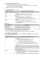
Character factory default


Setting item, function, setting range


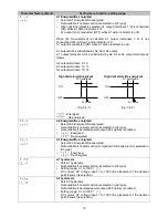
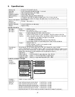
A1 Energized/De-energized 

•  Selects A1 Energized/De-energized. 

Not available if no alarm action is selected in [A1 type]. 

•  When [A1 Energized] is selected, A1 output (terminals 7, 8) is conducted 

(ON) while A1 action indicator is lit. 
A1 output is not conducted (OFF) while A1 action indicator is unlit. 
 

When  [A1  De-energized]  is  selected,  A1  output  (terminals  7,  8)  is  not 
conducted (OFF) while A1 action indicator is lit. 
A1 output is conducted (ON) while A1 action indicator is unlit. 
 
A1 output will be substituted by 

A2, A3 or A4 output.   

A1  output  terminals  will  be  substituted  by 

A2, A3  or A4 output  terminals as 

follows. 
 
A2 output terminals: 9, 10 
A3 output terminals: 12, 13 
A4 output terminals: 15, 16 
 

High limit alarm (Energized)


High limit alarm (De-energized)


(Fig. 5.4-1) 

(Fig. 5.4-2) 


: Energized 
  : De-energized 


A2 Energized/De-energized 

•  Selects A2 Energized/De-energized. 

Not available if no alarm action is selected in [A2 type]. 

•  Not available if insulated power output (P24 option) is ordered. 
• 

: Energized 
: De-energized 


A3 Energized/De-energized 

•  Selects A3 Energized/De-energized. 

Not available if no alarm action or high/low limit range alarm is selected in 
[A3 type]. 

• 

: Energized 
: De-energized 


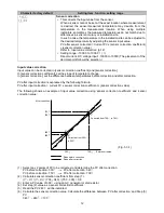
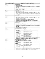
A1 hysteresis 

•  Sets A1 hysteresis. 
•  Not available if no alarm action is selected in [A1 type]. 
•  Setting range: 0.1 to 100.0   ( ) 

DC  current,  DC  voltage  input:  1  to  1000  (the  placement  of  the  decimal 
point follows the selection.) 


A2 hysteresis 

•  Sets A2 hysteresis. 
•  Not available if no alarm action is selected in [A2 type]. 

Not available if insulated power output (P24 option) is ordered. 

•  Setting range: 0.1 to 100.0   ( ) 

DC  current,  DC  voltage  input:  1  to  1000  (the  placement  of  the  decimal 
point follows the selection.) 
 

OFF

ON

A1 value

A1 hysteresis

OFF

ON

A1 value

A1 hysteresis

Summary of Contents for DI25

Page 1: ...DIGITAL INDICATOR DI25 Operating instructions ...

Page 2: ...fire only WIKA or other qualified service personnel may handle the inner assembly To prevent an electrical shock fire or damage to the instrument parts replacement may only be undertaken by WIKA or other qualified service personnel This is an equipment of the emission class A that is intended for operation in industrial environment It can cause interference under certain circumstances if operated ...

Page 3: ...this instrument directly on or near flammable material even though the case of this instrument is made of flame retardant resin 2 Wiring precautions Caution Do not leave wire remnants in the instrument as they could cause a fire or malfunction The terminal block of this instrument is designed to be wired from the upper side The lead wire must be inserted from the upper side of the terminal and fas...

Page 4: ... the power switched ON may result in severe injury or death due to electrical shock Use a soft dry cloth when cleaning the instrument Alcohol based substances may tarnish or deface the unit As the display section is vulnerable be careful not to put pressure on scratch or strike it with a hard object Further information Internet address www wika de www wika com Relevant data sheet AC 80 02 Applicat...

Page 5: ...ing the selected item or value 11 5 2 Alarm setting mode 11 5 3 Auxiliary function setting mode 1 11 5 4 Auxiliary function setting mode 2 13 5 5 Maintenance mode 18 6 Operation 19 6 1 Operation 19 6 2 Switching SV display indication 19 6 3 How to use the alarm output 19 6 4 How to use the event input function 19 7 Alarm Action 20 7 1 High limit alarm low limit alarm 20 7 2 High Low limit range al...

Page 6: ...types can be selected by keypad 2 Alarms A1 A2 and A3 outputs are standard features Alarm types 4 types for A1 A2 and 5 types for A3 as well as no alarm action and energized de energized can be selected 3 If transmitter supply output P24 option is ordered A2 output cannot be used 1 2 Product label Model labels are attached to the case and the inner assembly Top of the case Fig 1 2 1 No Description...

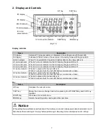
Page 7: ...ED flashes maintenance mode A2 action indicator When A2 output is ON the red LED is lit While A2 output is held the red LED flashes maintenance mode A3 action indicator When A3 output is ON the red LED is lit While A3 output is held the red LED flashes maintenance mode Key Name Description UP key Increases the numeric value FAST key Makes the set value change faster while pressing the UP DOWN key ...

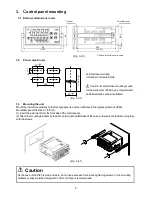
Page 8: ... ingress protection IP66 Mountable panel thickness 1 to 8 mm 1 Insert the instrument from the front side of the control panel 2 Attach the mounting brackets by the slots on the right and left sides of the case and secure the instrument in place with the screws Fig 3 4 1 Caution As the case of the DI25 is made of resin do not use excessive force while tightening screws or the mounting brackets or c...

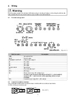
Page 9: ...in which an M3 screw fits as shown below 0 63 Nm of torque is recommended Terminal name Description GND Ground terminal PWR Power supply TRANSMIT OUTPUT1 Transmission output 1 A1 A1 output A2 A2 output A3 A3 output EVENT INPUT Event input TC Thermocouple input RTD RTD input DC Direct current input DC voltage input For direct current input externally mounted 50 shunt resistor connect a 50 shunt res...

Page 10: ... are in an OFF status Operation will then start indicating the PV process variable on the PV display and A1 A2 A3 value on the SV display Table 5 1 Sensor input PV display SV display PV display SV display K J R S B E T N PL C W Re5 26 Pt100 JPt100 Pt100 JPt100 4 20 mA DC 1 2 0 20 mA DC 1 2 0 1 V DC 1 0 5 V DC 1 1 5 V DC 1 0 10 V DC 1 4 20 mA DC 1 3 0 20 mA DC 1 3 Scaling high limit value 1 Input r...

Page 11: ...standby alarm Input range low limit to input range high limit 1 The placement of the decimal point follows the selection or input range 1 For DC current and DC voltage input setting range is scaling low limit to scaling high limit 5 3 Auxiliary function setting mode 1 To enter auxiliary function setting mode 1 press and hold the DOWN key and MODE key in that order together for approx 3 seconds in ...

Page 12: ...ensor correction coefficient set the slope of temperature change In sensor correction set the difference between temperatures before correction and after correction PV after input correction is expressed by the following formula PV after input correction current PV x sensor correction coefficient sensor correction value The following shows an example of input value correction using sensor correcti...

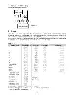
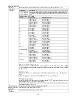
Page 13: ...the input is changed with the sensor connected the input circuit may break Table 5 4 1 Character Input range Character Input range K 200 to 1370 K 320 to 2500 K 200 0 to 400 0 K 200 0 to 750 0 J 200 to 1000 J 320 to 1800 R 0 to 1760 R 0 to 3200 S 0 to 1760 S 0 to 3200 B 0 to 1820 B 0 to 3300 E 200 to 800 E 320 to 1500 T 200 0 to 400 0 T 200 0 to 750 0 N 200 to 1300 N 320 to 2300 PL 0 to 1390 PL 0 ...

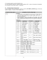
Page 14: ...r decimal point 3 digits after decimal point PV filter time constant Sets PV filter time constant If the value is set too large it affects alarm action due to the delay of response Setting range 0 0 to 10 0 sec A1 type Selects an A1 type See section 7 1 p 20 If A1 type is changed A1 value will default to 0 0 0 No alarm action High limit alarm Low limit alarm High limit with standby alarm Low limit...

Page 15: ...larm De energized Fig 5 4 1 Fig 5 4 2 Energized De energized A2 Energized De energized Selects A2 Energized De energized Not available if no alarm action is selected in A2 type Not available if insulated power output P24 option is ordered Energized De energized A3 Energized De energized Selects A3 Energized De energized Not available if no alarm action or high low limit range alarm is selected in ...

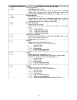
Page 16: ... Sets A3 action delay time When setting time has elapsed after the input enters the alarm output range the alarm is activated Not available if no alarm action or high low limit range alarm is selected in A3 type Setting range 0 to 9999 seconds Transmission output 1 high limit Sets the transmission output 1 high limit value Standard 4 20 mA DC Equals 20 mA DC output Optional 0 20 mA DC Equals 20 mA...

Page 17: ...cancelled by closing event input terminals 14 17 While the event input terminals 14 17 are closed the Alarm HOLD function will be disabled A1 HOLD function Enables Disables the A1 HOLD function Not available if no alarm action is selected in A1 type If A1 HOLD function is set to Enabled and if the alarm is ON the alarm output ON status will be maintained until the following is conducted The FAST k...

Page 18: ...e mode press the UP and FAST keys in that order together for approx 5 seconds in PV SV display mode If the unit enters maintenance mode all outputs are forced to turn OFF Character factory default Setting item function setting range A1 output ON OFF A1 output can be turned ON by the UP key and OFF by the DOWN key Not available if no alarm action is selected in A1 type Output OFF Output ON A2 outpu...

Page 19: ... value on the SV display and the A1 value indicator is lit Not available if no alarm action is selected in A1 type PV A2 value A2 value indication Indicates A2 value on the SV display and the A2 value indicator is lit Not available if no alarm action is selected in A2 type Not available if insulated power output P24 option is ordered PV A3 value A3 value indication Indicates A3 value on the SV dis...

Page 20: ...erminals are ON A1 A2 A3 action indicator is turned off when its output terminals are OFF A1 output terminals 7 8 ON A1 output terminals 7 8 ON or OFF A1 output terminals 7 8 OFF A1 output is in standby A1 hysteresis A1 value OFF ON OFF ON OFF ON OFF ON A1 hysteresis A1 hysteresis A1 hysteresis A1 value A1 value A1 value High limit alarm Low limit alarm High limit with standby alarm Low limit with...
Page 21: ...versa When standby function hysteresis or delay time for A1 and A2 are set check the below A3 action Please note the following If A1 or A2 with standby alarm is selected A3 is turned ON while A1 or A2 is in standby If A1 or A2 hysteresis increases A3 ON span decreases When A1 or A2 delay time setting time increases A3 ON time increases If A1 or A2 delay time setting time is set while A1 or A2 dela...

Page 22: ... resistive load Electrical life 100 000 cycles Transmission output 1 Converting the PV to analog signal every 125 ms outputs the value in direct current Unaffected by the HOLD function When using the Transmission output 1 value as an input for other instruments check that the input impedance of these instruments is smaller than the maximum load resistance of Transmission output 1 Resolution 12000 ...

Page 23: ...o 2365 0 to 4200 100 to 4300 Pt100 200 0 to 850 0 200 0 to 900 0 200 0 to 1000 0 200 0 to 1100 0 200 to 850 210 to 900 300 to 1500 318 to 1600 JPt100 200 0 to 500 0 200 0 to 550 0 200 0 to 900 0 200 0 to 1000 0 200 to 500 207 to 550 300 to 900 312 to 1000 Direct current DC voltage input If measured value exceeds Indication range high limit value the PV display flashes and if measured value drops b...

Page 24: ...and if a value around 0 32 is indicated the instrument is likely to be operating normally however the sensor may be burnt out DC voltage 0 to 1 V DC If the input terminals of the instrument are shorted and if a scaling low limit value is indicated the instrument is likely to be operating normally however the signal wire may be disconnected Check whether the input terminals of thermocouple RTD or D...

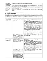
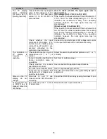
Page 25: ... 5 V DC 0 to 10 V DC or direct current 0 to 20 mA DC are securely connected to the instrument input terminals Connect the input terminals of DC voltage and current to the input terminals of this instrument securely The indication of PV display is irregular or unstable Check whether sensor input or temperature unit or is correct Select the sensor input and temperature unit or correctly Sensor corre...

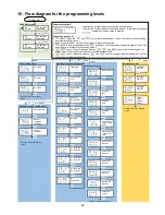
Page 26: ...utput ON OFF A3 output ON OFF Trans output 1 manual output Returns to PV SV display mode Auxiliary function setting mode 1 Set value lock Sensor correction coefficient Sensor correction Returns to PV SV display mode 3 sec 5 sec Power ON About setting item Upper left PV Display Indicates the setting item characters Lower left SV Display Indicates the factory default Right side Setting item Availabl...

Page 27: ...A must be free from any kind of hazardous substances acids bases solutions etc and must therefore be cleaned before being returned When returning the instrument use the original packaging or a suitable transport packaging To avoid damage 1 Wrap the instrument in an antistatic plastic film 2 Place the instrument along with shock absorbent material in the packaging Place shock absorbent material eve...

Page 28: ...28 14076218 02 05 2018 EN ...

Reviews: