46
10 Supplement
WIKA Operating Instructions - Process pressure transmitter IPT-1*
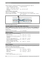
Thermal change zero signal and output span, reference temperature 20 °C (68 °F):
Ʋ
In the compensated temperature
range 0 … +100 °C (+32 … +212 °F)
< 0.05 %/10 K x TD
Ʋ
Outside the compensated tempera-
ture range
typ. < 0.05 %/10 K x TD
Thermal change, current output
Applies also to the
analogue
4 … 20 mA current output and refers to the set span.
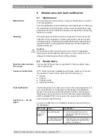
Thermal change, current output
< 0.05 %/10 K, max. < 0.15 %, each with -40 … +80 °C
(-40 … +176 °F)
0,3 %
-0,15 %
-40°C
-20°C
20°C
40°C
60°C
80°C
0,15 %
-0,3 %
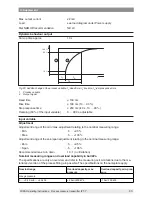
Fig. 24: Thermal change, current output
Long-term stability (according to DIN 16086 and IEC 60770-1)
Applies to
digital
interfaces (HART, Profibus PA, Foundation Fieldbus) as well as to
analogue
cur-
rent output 4 … 20 mA. Specifications refer to the set span. Turn down (TD) = nominal measuring
range/set span.
Long-term drift of the zero signal
< (0.1 % x TD)/year
Ambient conditions
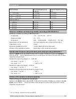
Ambient, storage and transport temperature
Ʋ
Standard version
-40 … +80 °C (-40 … +176 °F)
Ʋ Connection G1 A front-flush according
to EHEDG
-10 … +80 °C (+14 … +176 °F)
Ʋ
Version for oxygen applications
13)
-40 … +60 °C (-40 … +140 °F)
Ʋ
Versions IP 66/IP 68 (1 bar) and IP 68
(25 bar), connection cable PUR
-20 … +80 °C (-4 … +176 °F)
Ʋ
Version IP 66/IP 68 (1 bar), connec-
tion cable PE
-20 … +60 °C (-4 … +140 °F)
Process conditions
The specifications are used as an overview. For pressure stage and product temperature the speci
-
fications on the type plate are applicable.
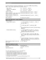
Product temperature standard, depending on the seal
14)
Ʋ
FKM (VP2/A)
-20 … +105 °C (-4 … +221 °F)
Ʋ
EPDM (A+P 75.5/KW75F)
-40 … +105 °C (-40 … +221 °F)
Ʋ NBR (COG)
-20 … +105 °C (-4 … +221 °F)
13)
Up to 60 °C (140 °F).
14)
Version for oxygen applications up to 60 °C (140 °F).

