6
S
et up with the indicating and adjustment
module
6
.
1
S
hort description
T
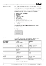
he indicating and adjustment module is used for measured value
display
,
adjustment and diagnosis
.
I
t can be mounted in the following
housing versions and instruments
:
l
A
ll sensors of the
IPT
-
1
*
instrument family
,
in the single as well as
double chamber housing
(
optionally in the electronics or connec
-
tion compartment
)
l
E
xternal indicating and adjustment unit
N
ote
:
Y
ou can
fi
nd detailed information on adjustment in the operating
instructions manual
"
I
ndicating and adjustment module
"
.
6
.
2
I
nsert indicating and adjustment module
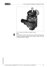
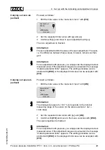
T
he indicating and adjustment module can be inserted and removed at
any time
.
I
t is not necessary to interrupt the voltage supply
.
F
or mounting
,
proceed as follows
:
1
U
nscrew the housing cover
2
P
lace the indicating and adjustment module in the desired position
on the electronics
(
you can choose any one of four di
ff
erent
positions
-
each displaced by
90
°
)
3
P
ress the indicating and adjustment module onto the electronics
and turn it to the right until it snaps in
.
4
S
crew housing cover with inspection window tightly back on
R
emoval is carried out in reverse order
.
T
he indicating and adjustment module is powered by the sensor
,
an
additional connection is not necessary
.
F
unction
/
C
on
fi
guration
M
ount
/
D
ismount indicat
-
ing and adjustment
module
20
P
rocess pressure transmitter
IPT
-
11
V
ers
.
4
.
0
-
ceramic sensor
•
P
ro
fi
bus
PA
6
S
et up with the indicating and adjustment module
31547
-
EN
-
081211


