2.3 Special hazards
WARNING!
Residual media in the dismounted instrument
can result in a risk to persons, the environment
and equipment.
Take sufficient precautionary measures.
2.4 Labelling, safety marking
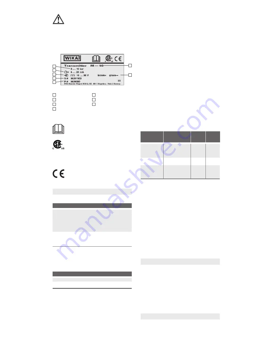
Product label
1
Measuring range
5
P# product number
2
Output signal
6
Model
3
Power supply
7
Pin assignment
4
S# serial number
Explanation of symbols
Before mounting and commissioning the
instrument, ensure you read the operating
instructions!
CSA, Canadian Standard Association
®
The instrument was inspected and certified
by CSA International. Instruments bearing this
mark comply with the applicable Canadian and
American standards on safety (including explo-
sion protection).
CE, Communauté Européenne
Instruments bearing this mark comply with the
relevant European directives.
3. Specifications
3.1 Measuring ranges
Relative pressure
bar Measuring range
0 ... 6
1)
0 ... 10
1)
0 ... 16
1)
0 ... 25
Overload safty
20
20
32
50
Measuring range
0 ... 40
0 ... 60
0 ... 100
0 ... 160
Overload safty
80
120
200
320
Measuring range
0 ... 250
0 ... 400
0 ... 600
0 ... 1,000
1)
Overload safty
500
800
1,200
1,500
psi
Measuring range
0 ... 500
0 ... 1,000
0 ... 3,000
0 ... 5,000
Overload safty
1,000
2,000
6,000
10,000
Measuring range
0 ... 10,000 0 ... 15,000
Overload safty
20,000
20,000
1) Only for model M-10
Vacuum tightness
Yes
3.2 Output signal
Signal type
Signal
Current (2-wire)
4 ... 20 mA
Voltage (3-wire)
DC 1 ... 5 V
DC 0.1 ... 10 V
Load in Ω
4 ... 20 mA:
≤ (power supply - 10 V) / 0.02 A
DC 1 ... 5 V:
> 10k
DC 0.1 ... 10 V:
> 20k
3.3 Voltage supply
Power supply
The power supply depends on the selected output signal
4 ... 20 mA:
DC 10 ...36 V
DC 1 ... 5 V:
DC 8 ... 36 V
DC 0.1 ... 10 V: DC 14 ...36 V
Total current consumption
Current output (2-wire): Signal current, max. 25 mA
Voltage output (3-wire):
8 mA
3.4 Operating conditions
Ingress protection (per IEC 60529)
For ingress protection see chapter 3.5 "Electrical connec
-
tions"
The stated ingress protection only applies when plugged
in using mating connectors that have the appropriate
ingress protection.
Temperatures
Medium:
-40 ... +100 °C
2)
Ambient:
-40 ... +100 °C
1) 2)
Storage:
-40 ... +100 °C
1) Instruments with cable outlet are only suitable for an ambient temperature of -40 ... +80 °C.
2) G ¼ B flush with NBR sealing: minimum permissible medium and ambient temperature -30 °C
Overload safety of the process connections
G ¼ B EN 837:
see chapter 3.1
G ¼ B flush:
see chapter 3.1
¼ NPT ANSI/ASME 1.20.1:
see chapter 3.1
G ¼ A DIN 3852-E:
600 bar
3.5 Electrical connections
Available connections
Electrical
connection
Ingress protection
Wire
cross-
section
Cable
diameter
Circular connector
M12 x 1 (4-pin)
Measuring range < 100 bar:
IP 65
1)
Measuring range > 100 bar:
IP 67
-
-
Angular connector
DIN EN 175301-803 C
IP 65
2)
-
1.5 ... 6.0 mm
Cable outlet, from
PUR, 2 m
3)
Measuring range < 100 bar:
IP 65
1)
Measuring range > 100 bar:
IP 67
3 x 0.14 mm
2 4)
4.5 ... 5.0 mm
1) IP 67 on request
2) For conductor cross-section to max. 0.75 mm
2
3) Permissible ambient temperature -40 ... + 80 °C
4) For wire cross-section to max. 0.3 mm
2
, approx. AWG 22 with end splices
The stated ingress protection only applies when plugged
in using mating connectors that have the appropriate
ingress protection.
3.6 CE conformity
■
EMC directive, EN 61326 emission (group 1, class B)
and immunity (industrial application)
■
Pressure equipment directive
■
RoHS directive
For further specifications see WIKA data sheet PE 81.25
and the order documentation.
4. Design and function
4.1 Description
By means of a sensor element and by supplying power,
the prevailing pressure is converted into an amplified
standardised electrical signal via the deformation of a
diaphragm. This electrical signal varies in proportion to the
pressure and can be evaluated accordingly.
4.2 Scope of delivery
Cross-check scope of delivery with delivery note.
5. Transport, packaging and storage
5.1 Transport
Check the pressure transmitter for any damage that may
have been caused during transportation.
Obvious damage must be reported immediately.
1
2
3
4
5
6
7


