background image

ES

WIKA manual de seguridad transmisor de temperatura T32.xS

54

11583631.04 10/2017 EN/DE/FR/ES

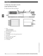
2.2  Rótulos, marcajes de seguridad
Placa de identificación (ejemplo)


Montaje en cabezal, modelo T32.1S

Modelo

con SIL: T32.1S.0IS-

S

sin SIL: T32.1S.0IS-

Z

Fecha de fabricación (año/mes)

Número de serie

Marcaje Ex

Logo de la homologación, versión SIL (solo con SIL)

Alimentación auxiliar

Señal de salida, 

versión 

HART

®

Sensor, Pt100 o RTD

Rango de medida

Número TAG

2. Seguridad

Summary of Contents for T32.1S.000-S

Page 1: ...ur funktionalen Sicherheit für Temperaturtransmitter Typ T32 xS Indications relatives à la sécurité fonctionnelle pour transmetteur de température type T32 xS Notas acerca de la seguridad funcional para transmisores de temperatura modelo T32 xS Head mounting version Rail mounting version model T32 1S model T32 3S Full assessment per IEC 61508 certified by TÜV Rheinland ...

Page 2: ...el T32 xS Page 3 20 Sicherheitshandbuch Typ T32 xS Seite 21 34 Manuel de sécurité type T32 xS Page 35 48 Manual de seguridad modelo T32 xS Página 49 62 11583631 04 10 2017 EN DE FR ES WIKA safety manual temperature transmitter T32 xS ...

Page 3: ...afety marking 8 2 3 Restrictions to operating modes 10 2 4 Error signaling 10 2 5 Write protection 11 2 6 Accuracy of the safe measuring function 12 2 7 Configuration changes 13 2 8 Commissioning and recurring tests 14 2 8 1 Proof test of the transmitter s complete signal processing chain 14 2 8 2 Reduced proof test limited testing of the transmitter s signal processing chain 15 2 9 Information on...

Page 4: ...S T32 3S temperature transmitters from firmware rev 2 2 3 only as a component of a safety function This safety manual applies in conjunction with the documentation mentioned under 1 2 Other applicable instrument documentation In addition the safety instructions in the operating instructions must be observed These operating instructions contain important information on working with the model T32 1S...

Page 5: ...f failures to danger that are detected by automatic diagnostic online tests FMEDA Failure modes effects and diagnostic analysis methods to detect failure causes and also their impact on the system and to define diagnostic measures HFT Hardware fault tolerance capability of a functional unit to continue the execution of the demanded function when faults or deviations exist MooN M out of N architect...

Page 6: ... of the model T32 xS temperature transmitter the following temperature sensors connected to the transmitter achieve a sufficient SFF Safe Failure Fraction for SIL 2 of 60 Thermocouples with internal or external Pt100 cold junction Type E J T U R S B K L N Resistance temperature sensors with 2 3 or 4 wire connection Pt100 JPt100 Ni100 Pt1000 Pt500 Pt25 Pt10 Dual thermocouples or dual resistance tem...

Page 7: ...voltage limits apply Instrument model Terminal voltage limits T32 1S 000 S T32 3S 000 S DC 10 5 42 V T32 1S 0IS S T32 3S 0IS S DC 10 5 30 V T32 1S 0NI S T32 3S 0NI S DC 10 5 40 V T32 1S 0IC S T32 3S 0IC S DC 10 5 30 V WARNING Only the temperature sensors listed in chapter 2 1 are approved for use in a safety related application The following sensors and operating modes are NOT allowed for operatio...

Page 8: ...1S 0IS S without SIL T32 1S 0IS Z Date of manufacture year month Serial number Ex marking Approval logos SIL version only for SIL Power supply Output signal HART version Sensor Pt100 or RTD Measuring range TAG no 2 2 Labelling safety marking Product label example Head mounting version model T32 1S 2 Safety ...

Page 9: ...ith SIL T32 3S 0IS S without SIL T32 3S 0IS Z Date of manufacture year month Ex marking Approval logos SIL version only for SIL Power supply Output signal HART version Pin assignment TAG no Measuring range Sensor Pt100 or RTD Serial number Before mounting and commissioning the instrument ensure you read the operating instructions 11 11 11 ...

Page 10: ...sor break Sensor short circuit only for resistance temperature sensors not for thermocouples Inadmissibly high lead resistance not with resistance temperature sensors with 2 wire connection The online diagnosis test interval of the instrument should be a maximum of 35 minutes This implies the discovery of the following potential instrument errors ROM error EEPROM error RAM error Program counter er...

Page 11: ...agnostic functions available over HART should be used Such functions are offered for example in the WIKA_T32 configuration software free download from www wika com 2 5 Write protection The T32 xS offers a write protection functionality in order to prevent accidental configuration changes The write protection password is factory set to 0 A T32 xS temperature transmitter with SIL option will only wo...

Page 12: ...en in the table the total safety accuracy is 2 of the measuring span with respect to the current output signal of 16 mA Otherwise the absolute values given directly in the table are valid CAUTION The measuring span is the difference between the full scale value and the initial value of a measuring range Sensor type Permissible sensor range for the accuracy specifications Min span for 2 total safet...

Page 13: ...A in terms of the current output 2 7 Configuration changes WARNING During the configuration change the safety function is not active Safe operation is only admissible with activated write protection password Carry out configuration changes within the permissible specifications in accordance with chapter 2 1 Intended use in safety applications With the supplied configuration tools such items as the...

Page 14: ...RT command 40 Enter fixed current mode 4 Test whether the current output signal reaches this value 5 With the aid of the function in simulation mode set the current output of the transmitter to a low alarm value 3 6 mA 6 Test whether the current output signal reaches this value 7 Activate the write protection and wait for a minimum of 5 seconds 8 Switch the instrument off or disconnect from the po...

Page 15: ... instructions 12 Remove the bypass on the safety controller system or restore the normal operating condition in a different way 13 Following the test the results must be documented and archived accordingly In contrast to the procedures described in 2 8 1 the signal processing chain is not tested here Its operational reliability should be ensured through reading the instrument status and evaluating...

Page 16: ...ure rates determined by Exida com LLC are used The following assumptions have been made The transmitter is only operated in Low Demand Mode applications The mean ambient temperature at the temperature transmitter during the period of operation is 40 C The MTTR following an instrument failure is 8 hours Following ISO 13849 1 a maximum service life in the safety application for the transmitter of 20...

Page 17: ... components Operating mode Low Demand Mode MTTR 8 h MRT ca 7 5 h Current hardware version 9 Current software version Firmware 2 2 3 2 3 1 Safety manual Issue 09 2017 Type of evaluation Complete evaluation in parallel with development of hardware and software incl FMEDA on a component level and change process to IEC 61508 2 3 Evaluation through Report No TÜV Rheinland xxxxxxxxxxx Test documents Saf...

Page 18: ... Pt100 2 wire Close coupled 1 Extension wire 2 Low stress 3 High stress 4 Low stress 3 High stress 4 λDU FIT 5 10 19 200 183 1 910 λDD FIT 5 73 112 835 860 7 673 λSU λSD FIT 5 76 76 76 76 76 SFF Sensor Transmitter 6 93 8 82 0 93 8 80 0 93 8 82 0 93 8 80 0 93 8 PFDavg for Tproof 1 year 7 4 33 10 5 8 12 10 5 8 76 10 4 8 01 10 4 8 37 10 3 DC diagnostic coverage 99 0 Page 2 4 SIL Declaration of Confor...

Page 19: ...tand alone T32 xS with duplex sensor Pt100 Close coupled 1 Extension wire 2 Low stress 3 High stress 4 Low stress 3 High stress 4 λDU FIT 5 10 27 390 356 3 810 λDD FIT 5 75 154 1 599 1 649 15 275 λSU λSD FIT 5 76 76 76 76 76 SFF Sensor Transmitter 6 93 8 82 0 93 8 80 0 93 8 82 0 93 8 80 0 93 8 PFDavg for Tproof 1 year 7 4 36 10 5 1 19 10 4 1 71 10 3 1 56 10 3 1 67 10 2 DC diagnostic coverage 99 0 ...

Page 20: ...mitter is located in the connection head of the electrical thermometer 2 Extension wire The temperature transmitter is located outside of the connection head of the electrical thermometer for example in a cabinet distant from the measuring point 3 Low stress applies to a low vibration environment or the use of a cushioned sensor Operation below 67 maximum rating according to specification 4 High s...

Page 21: ...ichnungen 26 2 3 Einschränkung der Betriebsarten 28 2 4 Fehlersignalisierung 28 2 5 Schreibschutz 29 2 6 Genauigkeit der sicheren Messfunktion 30 2 7 Konfigurationsänderungen 31 2 8 Inbetriebnahme und wiederkehrende Prüfungen 32 2 8 1 Wiederholungsprüfung der kompletten Signalverarbeitungskette des Transmitters 32 2 8 2 Reduzierte Wiederholungsprüfung eingeschränkte Prüfung der Signalverarbeitungs...

Page 22: ...itter Typ T32 1S T32 3S ab Firmware Rev 2 2 3 lediglich als Teil einer Sicherheits funktion Dieses Sicherheitshandbuch gilt im Zusammenhang mit den unter 1 2 Mitgelten de Gerätedokumentationen genannten Dokumentationen Zusätzlich die Sicherheitshin weise in der Betriebsanleitung beachten Die Betriebsanleitung enthält wichtige Hinweise zum Umgang mit dem Temperaturtrans mitter Typ T32 1S T32 3S Vor...

Page 23: ...en low demand In dieser Betriebsart wird die Sicherheitsfunktion des Sicherheitssystems nur auf Anforderung ausgeführt Die Häufigkeit der Anforderung beträgt nicht mehr als einmal je Jahr DC Diagnosedeckungsgrad Anteil der gefahrbringenden Ausfälle die durch automatische diagnostische Online Prüfungen erkannt werden FMEDA Failure Modes Effects and Diagnostic Analysis Verfahren um Fehlerursachen so...

Page 24: ...Das Gerät ist nach SIL 2 IEC 61508 zertifiziert Aufgrund der systemati schen Eignung des Transmitters für SC 3 ist es möglich abhängig von der Sicherheitsintegri tät der Hardware das Gerät in homogen redundanten Systemen bis SIL 3 einzusetzen Unter Berücksichtigung der Fehleraufdeckungsfunktionen des Temperaturtransmitters Typ T32 xS erreichen folgende an den Transmitter angeschlossenen Temperatur...

Page 25: ...n einhalten Gerätetyp Klemmenspannungsgrenzen T32 1S 000 S T32 3S 000 S DC 10 5 42 V T32 1S 0IS S T32 3S 0IS S DC 10 5 30 V T32 1S 0NI S T32 3S 0NI S DC 10 5 40 V T32 1S 0IC S T32 3S 0IC S DC 10 5 30 V WARNUNG Nur die unter Kapitel 2 1 aufgelisteten Temperatursensoren sind für den Einsatz in einer sicherheitsgerichteten Anwendung zulässig Folgende Sensoren und Betriebsarten sind für den Einsatz in...

Page 26: ...herheitskennzeichnungen Typenschild Beispiel Kopfversion Typ T32 1S Typ mit SIL T32 1S 0IS S ohne SIL T32 1S 0IS Z Herstellungsdatum Jahr Monat Seriennummer Ex Kennzeichnung Zulassungslogos SIL Ausführung nur bei SIL Hilfsenergie Ausgangssignal HART Version Sensor Pt100 oder RTD Messbereich TAG Nummer 2 Sicherheit ...

Page 27: ... T32 3S 0IS S ohne SIL T32 3S 0IS Z Herstellungsdatum Jahr Monat Ex Kennzeichnung Zulassungslogos SIL Ausführung nur bei SIL Hilfsenergie Ausgangssignal HART Version Anschlussbelegung TAG Nummer Messbereich Sensor Pt100 oder RTD Seriennummer Vor Montage und Inbetriebnahme des Gerätes unbedingt die Betriebsanleitung lesen 11 2 Sicherheit ...

Page 28: ...er Fühlerbruch Fühlerkurzschluss nur bei Widerstandstemperatursensoren nicht für Thermoelemente Unzulässig hoher Zuleitungswiderstand nicht bei Widerstandstemperatursensoren mit 2 Leiter Anschluss Das online Diagnose Test Intervall des Geräts beträgt maximal 35 Minuten Dies beinhaltet die Aufdeckung folgender potentieller Gerätefehler ROM Fehler EEPROM Fehler RAM Fehler Programm Counter Fehler Sta...

Page 29: ...n Diagnose Funktionen Derartige Funktionen bietet z B die Konfigurationssoftware WIKA_T32 an kostenfreier Download unter www wika de 2 5 Schreibschutz Der T32 xS verfügt über eine Schreibschutzfunktionalität um versehentliche Konfigura tionsänderungen zu verhindern Ab Werk ist das Passwort des Schreibschutzes auf 0 eingestellt Ein T32 xS Temperaturtransmitter mit SIL Option geht erst in den aktive...

Page 30: ...n der Tabelle angegebenen minimalen Spannen beträgt die Gesamtsicher heitsgenauigkeit 2 der Messspanne bzgl des Stromausgangssignals von 16 mA Ansonsten gelten die in der Tabelle direkt angegebenen absoluten Werte VORSICHT Die Messspanne ist die Differenz zwischen Endwert und Anfangswert eines Messbereiches Sensortyp Zulässiger Sensorbe reich für die Genauig keitsangaben Min Spanne für 2 Gesamtsic...

Page 31: ... 640 μA bzgl des Stromausgangs 2 7 Konfigurationsänderungen WARNUNG Während der Konfigurationsänderung ist die Sicherheitsfunktion nicht aktiv Der Safety Betrieb ist nur mit aktiviertem Schreibschutz Passwort erlaubt Konfigurationsänderungen innerhalb der zulässigen Spezifikationen gemäß 2 1 Bestim mungsgemäße Verwendung in Sicherheitsanwendungen durchführen Mit den aufgeführten Konfigurationswerk...

Page 32: ...nen Hochalarmwert 21 0 mA einzustellen HART Kommando 40 Enter Fixed Current Mode 4 Prüfen ob das Stromausgangssignal diesen Wert erreicht 5 Den Stromausgang des Messumformers mithilfe der Funktion im Simulationsmodus auf einen Tiefalarmwert 3 6 mA einstellen 6 Prüfen ob das Stromausgangssignal diesen Wert erreicht 7 Den Schreibschutz aktivieren und min 5 Sekunden warten 8 Das Gerät abschalten bzw ...

Page 33: ...berbrückung des Sicherheitssteuerungssystems entfernen oder den normalen Betriebszustand auf eine andere Weise wiederherstellen 13 Nach Durchführung des Tests müssen die Ergebnisse dokumentiert und entsprechend archiviert werden Im Gegensatz zu dem in 2 8 1 beschriebenen Verfahren wird hier die Signalverarbeitungskette nicht getes tet Deren Funktionstüchtigkeit soll durch Auslesen des Gerätezustan...

Page 34: ...die FMEDA herangezogen Dabei gelten die folgenden Annahmen Der Transmitter wird nur in Anwendungen niedriger Anforderungsrate eingesetzt Low Demand Mode Die mittlere Umgebungstemperatur am Temperaturtransmitter während der Betriebszeit beträgt 40 C Die MTTR nach einem Gerätefehler beträgt 8 Stunden In Anlehnung an die ISO 13849 1 wird von einer maximalen Gebrauchsdauer für den Transmitter in einer...

Page 35: ...oncernant les modes de fonctionnement 42 2 4 Signalement d erreurs 42 2 5 Protection en écriture 43 2 6 Précision de la fonction de mesure sécuritaire 44 2 7 Changements de configuration 45 2 8 Mise en service et tests récurrents 46 2 8 1 Test de vérification de la chaîne complète de traitement du signal du transmetteur 46 2 8 2 Test de vérification réduit contrôle restreint de la chaîne de traite...

Page 36: ... 2 2 3 seulement en tant que composant d une fonction de sécurité Ce manuel de sécurité s applique en conjonction avec la documentation mentionnée à 1 2 Autre documentation d instrument applicable Ce manuel de sécurité s applique en conjonction avec la documentation mentionnée au chapitre 1 2 Autre documentation d instrument applicable En outre les instructions de sécurité contenues dans le mode d...

Page 37: ...on de sécurité du système de sécurité n est effectuée que sur demande La fréquence de cette demande ne dépasse pas une fois par an DC Diagnostic coverage Couverture de diagnostic pourcentage d erreurs conduisant à un danger qui sont détectées par des tests de diagnostic en ligne automatiques FMEDA Failure modes effects and diagnostic analysis Modes d échec effets et analyse de diagnostic méthodes ...

Page 38: ...outes les fonctions de sécurité se rapportent exclusivement au signal de sortie analogique 4 20 mA L instrument est certifié selon SIL 2 IEC 61508 Grâce à la capacité systématique du transmetteur pour SC 3 il est possible en fonction de l intégrité de sécurité du hardware d utiliser l instrument dans des systèmes redondants homogènes allant jusqu à SIL 3 En prenant en compte les fonctions de détec...

Page 39: ...e la sortie de courant la tension aux bornes correcte doit être présente dans l instrument Les limites de tension aux bornes suivantes s appliquent Type d instrument Limites de tension aux bornes T32 1S 000 S T32 3S 000 S DC 10 5 42 V T32 1S 0IS S T32 3S 0IS S DC 10 5 30 V T32 1S 0NI S T32 3S 0NI S DC 10 5 40 V T32 1S 0IC S T32 3S 0IC S DC 10 5 30 V AVERTISSEMENT Seuls les capteurs de température ...

Page 40: ...urité Plaque signalétique exemple Version tête de canne type T32 1S Type avec SIL T32 1S 0IS S sans SIL T32 1S 0IS Z Date de fabrication année mois Numéro de série Marquage Ex Logo d agrément version SIL seulement pour SIL Alimentation Signal de sortie version HART Capteur Pt100 ou RTD Etendue de mesure N d étiquette 2 Sécurité ...

Page 41: ...s SIL T32 1S 0IS Z Date de fabrication année mois Marquage Ex Logo d agrément version SIL seulement pour SIL Alimentation Signal de sortie version HART Configuration du raccordement N d étiquette Etendue de mesure Capteur Pt100 ou RTD Numéro de série Lire impérativement le mode d emploi avant le montage et la mise en service de l instrument 11 11 11 2 Sécurité ...

Page 42: ... les capteurs de température de résistance et pas pour les thermocouples Niveau de résistance de l alimentation inadmissible pas pour des capteurs de température à résistance avec connexion à 2 fils L intervalle de test de diagnostic en ligne de l instrument doit être de 35 minutes au maximum Ceci implique la découverte des erreurs d instrument potentielles suivantes Erreur ROM Erreur EEPROM Erreu...

Page 43: ...eur il faudra utiliser les fonctions de diagnostic disponibles sur HART De telles fonctions sont proposées par exemple dans le logiciel de configuration WIKA_T32 téléchargement gratuit depuis www wika com 2 5 Protection en écriture Le T32 xS offre une protection en écriture pour prévenir des changements accidentels de configuration Le mot de passe de la protection en écriture est réglé en usine su...

Page 44: ...es dans le tableau la précision totale de sécurité est de 2 de l étendue de mesure en prenant en compte le signal de sortie de courant de 16 mA Sinon les valeurs absolues données directement dans le tableau sont valables ATTENTION L étendue de mesure est la différence entre la valeur pleine échelle et la valeur initiale d une plage de mesure Type de capteur Etendue de capteur admissible pour les s...

Page 45: ... 2 7 Changements de configuration AVERTISSEMENT Pendant le changement de configuration la fonction de sécurité n est pas active Un fonctionnement en toute sécurité n est permis qu avec la protection en écriture activée mot de passe Effectuez les changements de configuration dans les respect des spécifications admissibles en conformité avec le chapitre 2 1 Usage prévu dans des applications de sécur...

Page 46: ...rifier si le signal de sortie de courant atteint cette valeur 5 Au moyen de la fonction en mode simulation régler la sortie du courant du transmetteur sur une valeur d alarme basse 3 6 mA 6 Vérifier si le signal de sortie de courant atteint cette valeur 7 Activer la protection en écriture et attendre au moins 5 secondes 8 Déconnecter l instrument ou le séparer de l alimentation 9 Redémarrer l inst...

Page 47: ...système de l automate de sécurité ou rétablir l état de service normal d une autre manière 13 Après le test il convient de documenter les résultats et de les archiver de manière adéquate Contrairement au procédé décrit au point 2 8 1 la chaîne de traitement des signaux n est pas soumise à un test dans ce cas Sa fiabilité fonctionnelle doit être garantie par la lecture de l état de l instrument et ...

Page 48: ...ont utilisés Les hypothèses suivantes ont été émises Le transmetteur n est mis en oeuvre que dans des applications avec taux de sollicitation faible Low Demand Mode La température ambiante moyenne sur le transmetteur de température durant la période de fonctionnement est de 40 C Le MTTR après une erreur sur l instrument est de 8 heures Suivant ISO 13849 1 on prévoit une durée de fonctionnement max...

Page 49: ...dad 54 2 3 Limitación de los modos de funcionamiento 56 2 4 Señalización de errores 56 2 5 Protección de escritura 57 2 6 Exactitud de la función de medición segura 58 2 7 Modificaciones de configuración 59 2 8 Puesta en servicio y pruebas repetidas 60 2 8 1 Prueba proof de la completa cadena de procesamiento de señales del transmisor 60 2 8 2 Prueba proof reducida de la cadena de procesamiento de...

Page 50: ...KA modelos T32 1S T32 3S a partir de versión 2 2 3 del firmware únicamente como parte de una función de seguridad Este manual de seguridad es válido junto con la documentación mencionada bajo 1 2 Otra documentación relativa al instrumento Respetar adicionalmente las instrucciones de seguridad en el manual de instrucciones El manual de instrucciones contiene indicaciones importantes acerca del mane...

Page 51: ...ste modo de funcionamiento la función de seguridad del sistema de seguridad solo se ejecuta bajo demanda El número de demandas es inferior de una vez al año DC Cobertura de diagnóstico proporción de los fallos peligrosos detectados por las pruebas diagnósticas automáticas online FMEDA Failure Modes Effects and Diagnostic Analysis también AMFE por análisis modal de fallos y efectos procedimiento pa...

Page 52: ...icamente a la señal de salida analógica 4 20 mA El instrumento está certificado según SIL 2 IEC 61508 La idoneidad sistemática del transmisor para SC 3 permite en función de la integridad de seguridad del hardware utilizar el instrumento en sistemas homogéneos redundantes hasta SIL 3 Considerando las funciones de detección de fallos del transmisor de temperatura modelo T32 xS los siguientes sensor...

Page 53: ...onamiento seguro de la salida de corriente debe aplicarse en particular una tensión de bornes correcta en el instrumento Respetar los siguientes límites para la tensión en bornes Tipo de instrumento Límites de tensión en bornes T32 1S 000 S T32 3S 000 S DC 10 5 42 V T32 1S 0IS S T32 3S 0IS S DC 10 5 30 V T32 1S 0NI S T32 3S 0NI S DC 10 5 40 V T32 1S 0IC S T32 3S 0IC S DC 10 5 30 V ADVERTENCIA En a...

Page 54: ...d Placa de identificación ejemplo Montaje en cabezal modelo T32 1S Modelo con SIL T32 1S 0IS S sin SIL T32 1S 0IS Z Fecha de fabricación año mes Número de serie Marcaje Ex Logo de la homologación versión SIL solo con SIL Alimentación auxiliar Señal de salida versión HART Sensor Pt100 o RTD Rango de medida Número TAG 2 Seguridad ...

Page 55: ...1S 0IS Z Fecha de fabricación año mes Marcaje Ex Logo de la homologación versión SIL solo con SIL Alimentación auxiliar Señal de salida versión HART Detalles del conexionado Número TAG Rango de medida Sensor Pt100 o RTD Número de serie Es absolutamente necesario leer el manual de instrucciones antes del montaje y la puesta en servicio del instrumento 11 11 11 2 Seguridad ...

Page 56: ... Rotura de la sonda Cortocircuito de la sonda sólo sensores de resistencia no termopares Resistencia de alimentación demasiado alta no con sensores de resistencia dobles con conexión de 2 hilos El intervalo de prueba y diagnóstico en línea del instrumento es máx 35 minutos Esto incluye la detección de los siguientes errores potenciales del instrumento Error de ROM Error de EEPROM Error de RAM Erro...

Page 57: ...avés de HART Estas funciones están disponibles por ejemplo en el software de configuración WIKA_T32 descarga gratuita de www wika de 2 5 Protección de escritura El T32 xS dispone de una funcionalidad de protección de escritura para evitar modificaciones de configuración no intencionadas La contraseña de la protección de escritura estándar ajustada en la fábrica es 0 No se activará el modo de funci...

Page 58: ...cisión de la seguridad total es del 2 del alcance de medición o de la señal de salida de corriente de 16 mA hasta los alcances mínimos indicados en la tabla Por lo demás son válidos directamente los valores absolutos indicados en la tabla CUIDADO El alcance de medición es la diferencia entre el valor final y valor inicial de un rango de medida Tipo de sensor Rango admisible del sensor para los dat...

Page 59: ...specto a la salida de corriente 2 7 Modificaciones de configuración ADVERTENCIA La función de seguridad está desactivada durante las modificaciones de la configuración El modo seguro sólo es admisible si la protección de escritura contraseña está activada Modificar la configuración dentro de las especificaciones admisibles según 2 1 Uso conforme a lo previsto en aplicaciones de seguridad La protec...

Page 60: ...er Fixed Current Mode 4 Comprobar si la señal de salida de corriente alcanza este valor 5 Ajustar un valor bajo de alarma 3 6 mA para la salida de corriente del convertidor de medición mediante la función en modo de simulación 6 Comprobar si la señal de salida de corriente alcanza este valor 7 Activar la protección de escritura y esperar mín 5 segundos 8 Desconectar el instrumento o interrumpir la...

Page 61: ...uenteado del sistema de control de seguridad o volver a establecer el modo de funcionamiento normal de otra manera 13 Después de realizar la prueba deben documentarse y archivarse los resultados Al contrario del procedimiento descrito en 2 8 1 no se comprueba la cadena de procesamiento de señales Su capacidad funcional debe garantizarse mediante la lectura del estado del instrumento y la evaluació...

Page 62: ...ablecidas por la empresa Exida com LLC para FMEDA Son válidas las siguientes hipótesis El transmisor se utiliza únicamente en aplicaciones de baja demanda low demand mode La media de la temperatura ambiente en el transmisor de temperatura es de 40 C durante el servicio La MTTR después de un fallo es 8 horas Basado en ISO 13849 1 se presupone una utilización máxima de 20 años del transmisor en una ...

Page 63: ...11583631 04 10 2017 EN DE FR ES WIKA safety manual temperature transmitter T32 xS 63 ...

Page 64: ...2 132 406 info wika de www wika de 64 WIKA safety manual temperature transmitter T32 xS WIKA subsidiaries worldwide can be found online at www wika com WIKA Niederlassungen weltweit finden Sie online unter www wika de La liste des filiales WIKA dans le monde se trouve sur www wika fr Sucursales WIKA en todo el mundo puede encontrar en www wika es ...

Reviews: