GB
11258421.09
01/2012
GB/D
WIKA operating instructions temperature transmitter T32.xS
35
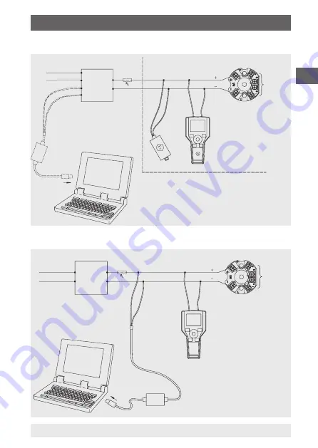
9.4.1 Typical connection for hazardous areas (head mounting)
9. Electrical connections
HART®
communicator
Transmitter
Hazardous area
Transmitter
Power supply
24 V
Safe area
11242175.02
9.4.2 Typical connection for non-hazardous areas
HART®
communicator
FSK modem
Transmitter
Non-hazardous areas
Transmitter
Power supply
24 V
11242299.02
RS 232-C
Bluetooth
Ex ia
USB
USB HART®
modem
Terminal 1-4:
sensor, see
designation
of terminal
connections
If RL is < 250 Ω in the respective
electrical circuit, RL must be increased
to at least 250 Ω by connecting external
resistances.
RL = Resistance for the HART
®
communication
RL min. 250 Ω, max. 1100 Ω
Terminal 1-4:
sensor, see
designation
of terminal
connections
If RL is < 250 Ω in the respective electrical
circuit, RL must be increased to at least
250 Ω by connecting external resistances.
RL = Resistance for the HART
®
communication
RL min. 250 Ω, max. 1100 Ω


