background image

D

WIKA Betriebsanleitung Temperatur-Transmitter T32.xS

11258421.09

 01/2012

 GB/D

59

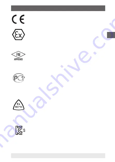
CE, Communauté Européenne

Geräte mit dieser Kennzeichnung stimmen überein mit 

den zutreffenden europäischen Richtlinien. 

ATEX Europäische Explosionsschutz-Richtlinie 

(Atmosphère = AT, explosible = EX)

Geräte mit dieser Kennzeichnung stimmen überein mit 

den Anforderungen der europäischen Richtlinie 94/9/EG 

(ATEX) zum Explosionsschutz.

FM, Factory Mutual

Das Gerät wurde von FM Approvals geprüft und zertifi-

ziert. Geräte mit dieser Kennzeichnung stimmen überein 

mit den anwendbaren US-amerikanischen Normen zur 

Sicherheit (einschließlich Explosionsschutz).

GOST, Gossudarstwenny Standart 

(Государственный Стандарт)

GOST-R (mark) 

Geräte mit dieser Kennzeichnung stimmen überein mit 

den anwendbaren nationalen Sicherheitsbestimmungen 

von Russland (Russische Föderation).

NEPSI, National supervision and inspection center for 

explosion protection and safety of instrumentation

Das Gerät wurde von NEPSI geprüft und zertifiziert. 

Geräte mit dieser Kennzeichnung stimmen überein mit 

den anwendbaren chinesischen Normen zur Sicherheit 

(einschließlich Explosionsschutz).

KOSHA, Korea Occupational Safety & Health Agency

Das Gerät wurde von KOSHA geprüft und zertifiziert. 

Geräte mit dieser Kennzeichnung stimmen überein mit 

den anwendbaren koreanischen Normen zur Sicherheit.

 2. Sicherheit

Summary of Contents for T32. S Series

Page 1: ...D GB Operating instructions Betriebsanleitung Head mounting version Rail mounting version model T32 1S model T32 3S Temperature transmitter model T32 xS Temperatur Transmitter Typ T32 xS ...

Page 2: ...vorbehalten WIKA is a registered trademark in various countries WIKA ist eine geschützte Marke in verschiedenen Ländern Prior to starting any work read the operating instructions Keep for later use Vor Beginn aller Arbeiten Betriebsanleitung lesen Zum späteren Gebrauch aufbewahren 11258421 09 01 2012 GB D WIKA operating instructions temperature transmitter T32 xS ...

Page 3: ...missioning operation 17 7 Notes for operating in safety related applications SIL 27 8 WIKA T32 configuration software 27 9 Electrical connections 30 10 Notes for mounting and operating in hazardous areas 36 4 11 Maintenance 41 12 Faults 42 13 Return and disposal 43 Appendix 1 FM CSA installation drawing 45 Appendix 2 EC declaration of conformity 47 Contents Declarations of conformity can be found ...

Page 4: ...nt s range of use The operating instructions are part of the instrument and must be kept in the immediate vicinity of the instrument and readily accessible to skilled personnel at any time Skilled personnel must have carefully read and understood the operating instructions prior to beginning any work The manufacturers liability is void in the case of any damage caused by using the product contrary...

Page 5: ...an result in light injuries or damage to equipment or the environment if not avoided Information points out useful tips recommendations and informa tion for efficient and trouble free operation DANGER identifies hazards caused by electrical power Should the safety instructions not be observed there is a risk of serious or fatal injury WARNING indicates a potentially dangerous situation hazardous a...

Page 6: ...ELV or PELV circuit is recommended alternatively protective measures from HD 60346 4 41 DIN VDE 0100 410 Alternatively for North America The connection can be made in line with Class 2 Circuits or Class 2 Power Units in accordance with CEC Canadian Electrical Code or NEC National Electrical Code Further important safety instructions can be found in the individual chapters of these operating instru...

Page 7: ... any type based on operation contrary to the intended use 2 2 Personnel qualification WARNING Risk of injury should qualification be insufficient Improper handling can result in considerable injury to personnel and damage to equipment The activities described in these operating instructions may only be carried out by skilled personnel who have the qualifications described below Keep unqualified pe...

Page 8: ...Do not use transmitters with any damage to the exterior 2 4 Special hazards WARNING Observe the information given in the applicable type examination certificate and the relevant country specific regulations for installation and use in hazardous areas e g IEC 60079 14 NEC CEC Non observance can result in serious injury and or damage to equipment For additional important safety instructions for inst...

Page 9: ...instructed in all topics regarding work safety first aid and environ mental protection and know the operating instructions and in particular the safety instructions contained therein WARNING When working during a running process operation measures to prevent electrostatic discharge from the connecting terminals should be taken as a discharge could lead to temporary corruption of the measured value...

Page 10: ...ion regulations for hazardous areas should be followed DANGER Danger of death caused by electric current Upon contact with live parts there is a direct danger of death The instrument may only be installed and mounted by skilled personnel Operation using a defective power supply unit e g short circuit from the mains voltage to the output voltage can result in life threatening voltages at the instru...

Page 11: ...D WIKA operating instructions temperature transmitter T32 xS 11 2 5 Versioning per NAMUR NE53 Version Notes Configuration WIKA_T32 software T32 HART instrument revision Corresponding DD 1 Device Description V2 1 3 first T32 xS version v1 50 3 Dev v3 DD v1 v2 2 1 T32 xS version with option SIL v1 51 3 Dev v3 DD v1 1 not yet available see chapter 6 3 2 DD version 2 6 Labelling safety labels Product ...

Page 12: ...mperature transmitter T32 xS Rail mounting version model T32 3S 2 Safety Explanation of symbols Before mounting and commissioning the instru ment ensure you read the operating instructions CSA Canadian Standard Association The instrument has been inspected and certified by CSA International Instruments bearing this mark comply with the applicable Canadian standards on safety including explosion pr...

Page 13: ...e US standards on safety including explosion protection GOST Gossudarstwenny Standart Государственный Стандарт GOST R mark Instruments bearing this mark comply with the applicable Russian national safety regulations Russian Federation NEPSI National supervision and inspection center for explosion protection and safety of instrumentation The instrument has been inspected and certified by NEPSI Inst...

Page 14: ...I 30 g and Type II 100 g Salt mist per IEC 60068 2 52 Severity level 1 Free fall drop per IEC 68 2 52 1996 Drop height 1500 mm Electromagnetic compatibility EMC EMC directive 2004 108 EC EN 61326 Emission Group 1 Class B and immunity industrial application Items in curved brackets are options for additional price not for rail mounting version T32 3S The models T32 1R and T32 3R temperature transmi...

Page 15: ...R recommendation NE21 Signalling at the analogue output in accordance with NAMUR recommendation NE43 Sensor burnout signalling in accordance with NAMUR recommen dation NE89 corrosion monitoring sensor connection 4 2 Operation in safety related applications The model T32 xS xxx S SIL version has been designed for use in safety related applications The marking of this design variant is given in chap...

Page 16: ...eported immediately 5 2 Packaging Do not remove packaging until just before mounting Keep the packaging as it will provide optimum protection during transport e g change in installation site sending for repair 5 3 Storage Permissible conditions at the place of storage Storage temperature 40 85 C Humidity 95 relative humidity Avoid exposure to the following factors Direct sunlight or proximity to h...

Page 17: ...is marked on the product label 6 1 Grounding Connection head BSS grounded Loop circuit Connection head BSS grounded grounded shield Thermowell with sensor grounded sensor wire equipotential bonding T32 xS Field housing switch cabinet For thermocouples additionally ground here The model T32 1S temperature transmitter should only be used with grounded thermometers For grounding of the model T32 xS t...

Page 18: ...ting space The connection wires of the measuring insert must be approx 50 mm long and insulated For applications with higher EMC requirements it is recommended using a shielded cable between the temperature transmitter and the sensor especially in connection with long leads to the sensor For an exemplary illustration see drawing grounded grounded shield sensor wire equipotential bonding T32 xS Fie...

Page 19: ...crew into the circular plate and verify length of 4 mm CAUTION Do not exceed the maximum permissible screw length The transmitter will be damaged if the screws are screwed further than 4 mm into the bottom of the transmitter Mounting in connection head Insert the measuring insert with the mounted transmitter into the protective sheath and secure into the connecting head using screws in pressure sp...

Page 20: ...0 If more than 2 sensors are connected dual sensor function further configurations can be carried out With the dual sensor function two identical sensors resistance sensor or thermocouple with the same measuring range are connected and then processed together The transmitters are delivered with a basic configuration see data sheet TE 32 04 or configured according to customer specifications If the ...

Page 21: ...output signal delivers the lower of the two values from sensor 1 and sensor 2 If one sensor fails the process value of the working sensor is output Maximum value The 4 20 mA output signal delivers the higher of the two values from sensor 1 and sensor 2 If one sensor fails the process value of the working sensor is output Difference The 4 20 mA output signal delivers the difference between sensor 1...

Page 22: ... from the working sensor only Once the error is rectified the process value will again be based on the two sensors or on sensor 1 Ageing monitoring sensor drift monitoring An error signal on the output is activated if the value of the tempe rature difference between sensor 1 and sensor 2 is higher than a set value which can be selected by the user This monitoring only generates a signal if two val...

Page 23: ... chapter 8 WIKA T32 configuration software WIKA T32 configuration software We recommend using our WIKA T32 configuration software This software is regularly updated and adapted to the firmware extensions of the T32 so that you always have full access to all functionalities and parameters of the transmitter see chapter 8 WIKA T32 configuration software Further configuration software With the follow...

Page 24: ...0 175 6 3 3 HART communicator HC275 FC375 FC475 MFC4150 With the HART communicator the instrument functions are selected via various menu levels and with the help of a special HART function matrix see chapter 6 5 HART configuration tree 6 4 Connection of FSK modem HART communicator WARNING The measuring circuit has to have a load of at least 250 Ω For all transmitters with hazardous area protectio...

Page 25: ...tion 2 Process adaption Sensor 1 3 Process adaption Sensor 2 4 Reset values 1 PV LSL 2 PV USL 3 PV Min span 4 Sensor operation 5 QV 4V Info 6 Custom sensor 7 Custom sensor info 1 Process variables 2 Diag Service 3 Basic setup 4 Detailed setup 5 Review 6 Write protection 7 Write protect T32 1 Test device 2 Loop test 3 Calibration 4 Device temp drag pointer 5 Set error dir 1 PV 2 PV Snsr unit 3 PV S...

Page 26: ...evice temp low 3 Reset rec device 1 Snsr damp 2 Set output range 3 AI range 1 Analog output 2 HART output 1 AO1 2 Output limits 3 Loop test 4 D A trim 1 Poll addr 2 Num req preambles 3 Burst mode 4 Burst option 5 HART device malfunction 1 Alarm level values 2 Set error direction 3 Monitor output limits 4 Monitor Tambient 1 Distributor 2 Model 3 Type code 4 Dev id 5 Tag 6 Date 7 Write protection 8 ...

Page 27: ...xx S SIL version has been designed for use in safety related applications For operation in safety related applications the additional requirements must be observed see safety manual Information on functional safety of model T32 xS The instructions contained in this must be followed without fail 8 WIKA T32 configuration software For installation please follow the instructions of the installation in...

Page 28: ... the software will try to establish a Multidrop connection The addresses 1 15 will be successively connected and will try to establish communication to a connected device Connection is only possible to a single instrument at any one time After successful connection the software shows the basic data for the connected instrument TAG mark Description User message Serial number Instrument model and ve...

Page 29: ... result of this Once the data has been correctly transferred confirm with OK Access to all operation relevant functions and parameters such as Sensor type and connection Measuring range and temperature unit Output signal Output limits and error signalling TAG of test point HART poll address Burst mode For further information on configuration see contact data on page 4 8 WIKA T32 configuration soft...

Page 30: ...rking on the transmitters e g installation removal maintenance work take measures to prevent electrostatic discharge from the terminals WARNING Only carry out installation in a de energised state The connected wires must be checked to ensure they are connected properly Only well secured wires can guarantee a fault free operation Input Sensor Output 4 20 mA loop For head mounting and rail mounting ...

Page 31: ...minal marked with With flexible leads we recommend the use of crimped connector sleeves The integrated reverse polarity protection wrong polarity on the terminals and prevents the transmitter from damage The following maximum values are applicable Model T32 xx 000 DC 42 V Model T32 xx 0IS DC 30 V Model T32 xx 0NI DC 40 V The T32 xS temperature transmitter requires a minimum terminal voltage of DC ...

Page 32: ...r the power supply for UB 42 V DC 5 A For the external power supply a separate switch is required 9 2 HART loop display DIH50 Additional configuration of the temperature transmitter with a HART Loop Display model DIH50 is possible This is used for the local display of the current process value The unit and the configured measuring range of the transmitter are automatically updated via the HART pro...

Page 33: ...atch with the actual method of connection used Otherwise you will not fully exploit the possibilities of connection lead compensation and as a result possibly cause additional measuring errors see chapter 6 3 Configuration 9 3 3 Thermocouples TC It is possible to connect one or two identical thermocouples Make sure that the thermocouple is connected with the correct polarity If the lead between th...

Page 34: ...wever the load must not be too high as otherwise in the case of relatively high currents the terminal voltage at the transmitter will be too low For that reason connect the cable clamps of the modem and or the HART communicator as described see chapter 6 5 HART configuration tree or use the existing communication connectors of a power supply line transformer The connection of the HART modem and or...

Page 35: ...nsmitter Power supply 24 V 11242299 02 RS 232 C Bluetooth Ex ia USB USB HART modem Terminal 1 4 sensor see designation of terminal connections If RL is 250 Ω in the respective electrical circuit RL must be increased to at least 250 Ω by connecting external resistances RL Resistance for the HART communication RL min 250 Ω max 1100 Ω Terminal 1 4 sensor see designation of terminal connections If RL ...

Page 36: ...n certificate Certification No BVS 08 ATEX E 019 X 10 1 Model overview and their European approvals Model Ex protection and approval no Ignition protection type T32 1S 0IS head mounting version II 1G Ex ia IIC T4 T5 T6 II 1D Ex iaD 20 T120 C intrinsically safe equipment T32 3S 0IS rail mounting version II 1G 2G Ex ia IIC T4 T5 T6 II 1D 2D Ex iaD 20 21 T120 C intrinsically safe equipment T32 xx 0NI...

Page 37: ... ingress protection IP 54 according to EN 60529 IEC 60529 T32 xx 0NI use as non incentive equipment II 3G Ex nA Disconnection of power supply is forbidden inside the hazardous area When connecting or disconnecting the terminals ensure the power supply is disconnected outside the hazardous area These temperature transmitters must be mounted in a case that must at least correspond to following ingre...

Page 38: ...the transmitter must be built into a housing which guarantees at least protection class IP 20 in accordance with EN 60529 and inside of which electrostatic discharges can be eliminated During installation in areas with 2D requirements the following must be observed Due to its design the transmitter must be built into a housing suitable for installation in areas with 2D requirements which guarantee...

Page 39: ...l T32 xx 0NI shall be installed in a pollution degree 2 environment or better in the end use appli cation for use with an IP 54 minimum enclosure provided by end user Operation in zone 0 The temperature transmitter may only be operated in areas requiring category 1 equipment when the following atmospheric conditions exist Temperature 20 60 C Pressure 0 8 1 1 bar Operation in zone 1 and zone 2 In a...

Page 40: ...egligible negligible Max external capacitance Co IIC 24 µF 1 1 000 µF IIB iaD 570 µF 1 IIA 1 000 µF 1 Max external inductance Lo IIC 365 mH 1 000 mH IIB iaD 1 644 mH IIA 3 288 mH Max inductance resistance ratio Lo Ro IIC 1 44 mH Ω 9 mH Ω IIB iaD 5 75 µH Ω IIA 11 5 µH Ω Characteristic curve linear n a not applicable 1 Ci already incorporated Notes Uo max voltage of any conductor against the other t...

Page 41: ...oes not have to be 23 mA The supply and signal circuit and the intrinsically safe sensor circuit must be considered as galvanically connected to each other 10 3 3 Connection of the HART modem HART communicator terminal and The sum of all voltages connected supply plus output values of the HART modem and or HART Communicator must not exceed 30 V for T32 xx 0IS and 40 V for T32 xx 0NI The sum of the...

Page 42: ...mitter is heating up or cooling down Process temperature out of range Wrong sensor connection Sensor burnout or short circuit Wrong transmitter configuration Capacitive or inductive coupling over the sensor Capacitive or inductive coupling over the loop Wrong polarity of thermocouple Loop resistance too high Electromagnetic interferences Linearization error for sensor transmitter Current value fal...

Page 43: ...rn and enclose a short description of the problem details of ambient conditions as well as period of operation before the problem occurred with the temperature transmitter 13 Return and disposal WARNING Residual media in the dismounted instrument can result in a risk to personnel the environment and equipment Take sufficient precautionary measures 13 1 Return WARNING Strictly observe the following...

Page 44: ... If possible place a bag containing a desiccant inside the packaging 4 Label the shipment as transport of a highly sensitive measuring instrument Enclose the completed return form with the instrument The return form is available in the Service section on www wika com 13 2 Disposal Incorrect disposal may endanger the environment Dispose of instrument components and packaging materials in an environ...

Page 45: ...GB 11258421 09 01 2012 GB D WIKA operating instructions temperature transmitter T32 xS 45 Appendix 1 FM CSA Installation drawing ...

Page 46: ...GB 11258421 09 01 2012 GB D 46 WIKA operating instructions temperature transmitter T32 xS Appendix 1 FM CSA installation drawing ...

Page 47: ...GB 11258421 09 01 2012 GB D WIKA operating instructions temperature transmitter T32 xS 47 Appendix 2 EC declaration of conformity ...

Page 48: ...GB 11258421 09 01 2012 GB D 48 WIKA operating instructions temperature transmitter T32 xS ...

Page 49: ...me Betrieb 63 7 Hinweise zum Einsatz in sicherheits gerichteten Anwendungen SIL 73 8 WIKA T32 Konfigurationssoftware 73 9 Elektrische Anschlüsse 76 10 Hinweise zu Montage und Betrieb im explosionsgefährdeten Bereich 82 11 Wartung 87 12 Störungen 88 13 Rücksendung und Entsorgung 89 Anlage 1 FM CSA Installation drawing 45 Anlage 2 EG Konformitätserklärung 47 Inhalt Konformitätserklärungen finden Sie...

Page 50: ...erhütungsvorschriften und allgemeinen Sicherheitsbestimmungen einhalten Die Betriebsanleitung ist Produktbestandteil und muss in unmittel barer Nähe des Gerätes für das Fachpersonal jederzeit zugänglich aufbewahrt werden Das Fachpersonal muss die Betriebsanleitung vor Beginn aller Arbeiten sorgfältig durchgelesen und verstanden haben Die Haftung des Herstellers erlischt bei Schäden durch bestim mu...

Page 51: ...rletzungen bzw Sach und Umweltschäden führen kann wenn sie nicht gemieden wird Information hebt nützliche Tipps und Empfehlungen sowie Infor mationen für einen effizienten und störungsfreien Betrieb hervor GEFAHR kennzeichnet Gefährdungen durch elektrischen Strom Bei Nichtbeachtung der Sicherheitshinweise besteht die Gefahr schwerer oder tödlicher Verletzungen WARNUNG weist auf eine möglicherweise...

Page 52: ...tromkreise alternativ ist eine Schutzmaß nahme aus HD 60346 4 41 DIN VDE 0100 410 zu empfehlen Alternativ für Nordamerika Der Anschluss kann auch an Class 2 Circuits oder Class 2 Power Units gemäß CEC Canadian Electrical Code oder NEC National Electrical Code erfolgen Weitere wichtige Sicherheitshinweise befinden sich in den einzelnen Kapiteln dieser Betriebsanleitung 2 1 Bestimmungsgemäße Verwend...

Page 53: ...on nicht bestimmungsgemäßer Verwendung sind ausgeschlossen 2 2 Personalqualifikation WARNUNG Verletzungsgefahr bei unzureichender Qualifikation Unsachgemäßer Umgang kann zu erheblichen Personen und Sachschäden führen Die in dieser Betriebsanleitung beschriebenen Tätigkeiten nur durch Fachpersonal nachfolgend beschriebener Qualifikation durchführen lassen Unqualifiziertes Personal von den Gefahrenb...

Page 54: ...Transmitter nicht verwenden 2 4 Besondere Gefahren WARNUNG Die Angaben der geltenden Baumusterprüfbescheini gung sowie die jeweiligen landesspezifischen Vorschrif ten zur Installation und Einsatz in explosionsgefährdeten Bereichen z B IEC 60079 14 NEC CEC einhalten Bei Nichtbeachten können schwere Körperverletzungen und oder Sachschäden auftreten Weitere wichtige Sicherheitshinweise für Geräte mit...

Page 55: ...ref fenden Fragen von Arbeitssicherheit Erste Hilfe und Umweltschutz unterwiesen wird sowie die Betriebs anleitung und insbesondere die darin enthaltenen Sicherheitshinweise kennt WARNUNG Bei Arbeiten während eines laufenden Prozessbetriebes Maßnahmen zur Vermeidung elektrostatischer Entladung auf die Anschlussklemmen treffen da Entladungen zu vorübergehenden Verfälschungen des Messwertes führen k...

Page 56: ...ür explosionsgefährdete Bereiche beachten GEFAHR Lebensgefahr durch elektrischen Strom Bei Berührung mit spannungsführenden Teilen besteht unmittelbare Lebensgefahr Einbau und Montage des Gerätes dürfen nur durch Fachpersonal erfolgen Bei Betrieb mit einem defekten Netzgerät z B Kurzschluss von Netzspannung zur Ausgangs spannung können am Gerät lebensgefährliche Spannungen auftreten WARNUNG Nur Ge...

Page 57: ...mitter T32 xS 11258421 09 01 2012 GB D 57 2 5 Versionierung nach NAMUR NE53 Version Bemerkungen Konfiguration WIKA_T32 Software T32 HART Geräte revision Zugehörige DD 1 Device Description V2 1 3 erste T32 xS Version v1 50 3 Dev v3 DD v1 v2 2 1 T32 xS Version mit Option SIL v1 51 3 Dev v3 DD v1 1 noch nicht verfügbar siehe Kapitel 6 3 2 DD Version 2 6 Beschilderung Sicherheitskennzeichnungen Typens...

Page 58: ... Temperatur Transmitter T32 xS Schienenversion Typ T32 3S 2 Sicherheit Symbolerklärung Vor Montage und Inbetriebnahme des Gerätes unbedingt die Betriebsanleitung lesen CSA Canadian Standard Association Das Gerät wurde durch CSA International geprüft und zertifiziert Geräte mit dieser Kennzeichnung stimmen überein mit den anwendbaren kanadischen Normen zur Sicherheit einschließlich Explosionsschutz...

Page 59: ...schen Normen zur Sicherheit einschließlich Explosionsschutz GOST Gossudarstwenny Standart Государственный Стандарт GOST R mark Geräte mit dieser Kennzeichnung stimmen überein mit den anwendbaren nationalen Sicherheitsbestimmungen von Russland Russische Föderation NEPSI National supervision and inspection center for explosion protection and safety of instrumentation Das Gerät wurde von NEPSI geprüf...

Page 60: ... IEC 60068 2 52 Schärfegrad 1 Freifall nach IEC 68 2 52 1996 Fallhöhe 1500 mm Elektromagnetische Verträglichkeit EMV EMV Richtlinie 2004 108 EG EN 61326 Emission Gruppe 1 Klasse B und Störfestigkeit industrieller Bereich sowie nach NAMUR NE21 Angaben in geschweiften Klammern beschreiben gegen Mehrpreis lieferbare Sonder heiten nicht für Schienenversion T32 3S Die Temperatur Transmitter Typen T32 1...

Page 61: ...lung NE21 Die Signalisierung am Analogausgang gemäß NAMUR Empfehlung NE43 Eine Fühlerbruchsignalisierung gemäß NAMUR Empfehlung NE89 Korrosionsüberwachung Sensoranschluss 4 2 Einsatz in sicherheitsgerichteten Anwendungen Option Der Typ T32 xS xxx S Ausführung SIL ist für den Einsatz in sicherheitsgerichteten Anwendungen konzipiert Die Kennzeichnung dieser Ausführungsvariante ist in Kapitel 2 6 Bes...

Page 62: ...ckung erst unmittelbar vor der Montage entfernen Die Verpackung aufbewahren denn diese bietet bei einem Transport einen optimalen Schutz z B wechselnder Einbauort Reparatur sendung 5 3 Lagerung Zulässige Bedingungen am Lagerort Lagertemperatur 40 85 C Feuchtigkeit 95 relative Feuchte Vermeidung folgender Einflüsse Direktes Sonnenlicht oder Nähe zu heißen Gegenständen Mechanische Vibration Ruß Damp...

Page 63: ... Bereich nur Temperatur Trans mitter einsetzen die für diesen explosionsgefährdeten Bereich zugelassen sind Die Zulassung ist auf dem Typenschild vermerkt 6 1 Erdung 6 Inbetriebnahme Betrieb Anschlusskopf BSS geerdet Schirm geerdet Schutzrohr mit Sensor geerdet Sensorleitung Potentialausgleich T32 xS Feldgehäuse Schaltschrank Bei Thermoelementen zusätzlich hier erden Zur Erdung des Temperatur Tran...

Page 64: ...nen mit erhöhten EMV Anforderungen empfiehlt sich v a in Verbindung mit langen Zuleitungen zum Sensor der Einsatz einer geschirmten Leitung zwischen Transmitter und Sensor Beispielhafte Darstellung siehe Zeichnung Montagebeispiel 3173801 A 6 2 Montage 6 2 1 Transmitter in Kopfversion Typ T32 1S Die Transmitter in Ausführung Kopfversion Typ T32 1S sind vorge sehen zur Montage auf einem Messeinsatz ...

Page 65: ...ei korrekt ausgeführter Senkung aus Vor dem Einschrauben die Schraubenlänge prüfen Schraube in die Ronde einstecken und das Maß 4 mm nachmessen 3173801 C VORSICHT Maximal zulässige Schraubenlänge nicht überschreiten Beschädigung des Temperatur Transmitters falls die Schraube mehr als 4 mm in den Transmitterboden einge schraubt wird Montage im Anschlusskopf Messeinsatz mit montiertem Transmitter in...

Page 66: ...Prozesswert linear transformiert werden Anwender Linearisierung Mittels Software können kundenspezifische Sensorkennlinien im Transmitter abgelegt werden um weitere Sensortypen abbilden zu können Anzahl der Stützstellen min 2 max 30 Bei Anschluss von 2 Sensoren Doppelsensorfunktion können weitere Konfigurationen vorgenommen werden Bei der Doppelsensorfunktion werden zwei gleiche Sensoren Widerstan...

Page 67: ...geben Minimalwert Das Ausgangssignal 4 20 mA liefert den Minimalwert bezogen auf Sensor 1 und Sensor 2 Fällt ein Sensor aus wird der Prozesswert des fehlerfreien Sensors ausgegeben Maximalwert Das Ausgangssignal 4 20 mA liefert den Maximalwert bezogen auf Sensor 1 und Sensor 2 Fällt ein Sensor aus wird der Prozesswert des fehlerfreien Sensors ausgegeben Differenz Das Ausgangssignal 4 20 mA liefert...

Page 68: ...n Sensor Ist der Fehler behoben basiert der Prozesswert wieder auf beiden Sensoren bzw auf Sensor 1 Alterungs Überwachung Sensor Drift Überwachung Es wird eine Fehlersignalisierung am Ausgang erzeugt wenn der Betrag der Temperaturdifferenz zwischen Sensor 1 und Sensor 2 größer wird als ein vom Anwender wählbarer Wert Diese Überwachung führt nur dann zur Signalisierung wenn zwei gültige Sensorwerte...

Page 69: ... Kapitel 8 WIKA T32 Konfi gurationssoftware verwendet werden Konfigurationssoftware WIKA T32 Empfohlen wird die Nutzung der WIKA T32 Konfigurationssoftware Diese wird ständig aktualisiert und den Firmware Erweiterungen des T32 angepasst Somit ist immer der volle Zugriff auf alle Funktionali täten und Parameter des Transmitters gewährleistet siehe Kapitel 8 WIKA T32 Konfigurationssoftware Weitere K...

Page 70: ...RT Communicator HC275 FC375 FC475 MFC4150 Das Anwählen der Gerätefunktionen erfolgt beim HART Communicator über verschiedene Menüebenen sowie mit Hilfe einer speziellen HART Funktionsmatrix siehe Kapitel 6 5 HART Konfigurationsbaum 6 4 FSK Modem HART Communicator anschließen WARNUNG Der Messkreis muss eine Bürde von mindestens 250 Ω aufweisen Bei allen Transmittern mit Ex Schutz Kapitel 10 Hinweis...

Page 71: ... Process adaption Sensor 1 3 Process adaption Sensor 2 4 Reset values 1 PV LSL 2 PV USL 3 PV Min span 4 Sensor operation 5 QV 4V Info 6 Custom sensor 7 Custom sensor info 1 Process variables 2 Diag Service 3 Basic setup 4 Detailed setup 5 Review 6 Write protection 7 Write protect T32 1 Test device 2 Loop test 3 Calibration 4 Device temp drag pointer 5 Set error dir 1 PV 2 PV Snsr unit 3 PV Snsr s ...

Page 72: ...ce temp low 3 Reset rec device 1 Snsr damp 2 Set output range 3 AI range 1 Analog output 2 HART output 1 AO1 2 Output limits 3 Loop test 4 D A trim 1 Poll addr 2 Num req preambles 3 Burst mode 4 Burst option 5 HART device malfunction 1 Alarm level values 2 Set error direction 3 Monitor output limits 4 Monitor Tambient 1 Distributor 2 Model 3 Type code 4 Dev id 5 Tag 6 Date 7 Write protection 8 Wri...

Page 73: ...erichteten Anwendungen konzipiert Für den Einsatz in sicherheitsgerichteten Anwendungen sind zusätzliche Bedingungen zu beachten siehe Sicherheitshandbuch Hinweise zur funktionalen Sicherheit des Typs T32 xS Die darin enthaltenen Hinweise sind unbedingt zu beachten 8 WIKA T32 Konfigurationssoftware Zur Installation den Anweisungen der Installationsroutine folgen Kostenfreier Download der aktuellen...

Page 74: ...gestellt Bleibt dieser Verbindungs versuch erfolglos werden nacheinander die Kurzadressen 1 15 angesprochen Verbindungsaufnahme jeweils nur zu einem Gerät möglich Nach erfolgreichem Verbindungs aufbau zeigt die Software grund legende Daten des angeschlos senen Gerätes TAG Kennzeichen Beschreibung Anwendernachricht Seriennummer Gerätetyp und version Hersteller sowie den benutzten Port des PC s Verb...

Page 75: ... Bei ordnungsgemäßem Auslesen der Daten nun mit OK bestätigen Zugriff auf betriebs relevante Funktionen und Parameter wie Sensorart und anschluss Messbereich und Temperatureinheit Ausgangssignal Ausgangsgrenzen und Fehler signalisierung Kennzeichnung der Messstelle HART Kurzadresse Burstmodus Für weitere Informationen zur Konfiguration siehe Kontaktdaten auf Seite 50 8 WIKA T32 Konfigurationssoftw...

Page 76: ...ehe Kapitel 10 3 Sicherheitstechnische Maximalwerte beachten Bei Arbeiten an den Transmittern z B Ein Ausbau Wartungsarbeiten Maßnahmen zur Vermeidung von elektrostatischen Entladungen auf die Anschlussklemmen treffen WARNUNG Montagen im spannungslosen Zustand durchführen Eingang Sensor Ausgang 4 20 mA Schleife Bei Kopf und Schienengehäuse sind Anschlussösen für das HART Modem vorhanden 9 Elektris...

Page 77: ...n die mit gekennzeichnete Klemme den Minuspol der Hilfsenergie an die mit gekennzeichnete Klemme anschließen Empfohlen wird bei Litzenadern die Verwenden von Crimpkontakten Der integrierte Verpolschutz verpolte Spannung an den Klemmen und verhindert die Zerstörung des Transmitters Dabei gelten die folgenden maximalen Werte Typ T32 xx 000 DC 42 V Typ T32 xx 0IS DC 30 V Typ T32 xx 0NI DC 40 V Der Te...

Page 78: ... V DC 5 A Für die externe Stromversorgung einen separaten Schalter vorsehen 9 2 HART Loop Anzeige DIH50 Zusätzliche Ausstattung des Temperatur Transmitters mit einer HART Loop Anzeige Typ DIH50 möglich Diese dient zur Visualisierung des aktuellen Prozesswertes Die Einheit und der konfigurierte Messbereich des Temperatur Transmitters werden automatisch über das HART Protokoll in der Anzeige aktuali...

Page 79: ...lussschaltung konfigurieren ansonsten keine vollständige Nutzung der Möglichkeiten der Anschlussleitungskompensation und eventuelle Verursachung zusätzlicher Messfehler siehe Kapitel 6 3 Konfiguration 9 3 3 Thermoelemente TE Möglich ist der Anschluss von einem oder zwei gleichen Thermo elementen Auf polaritätsrichtigen Anschluss des Thermoelementes achten Nur Thermo bzw Ausgleichsleitungen entspre...

Page 80: ...llerdings darf die Bürde nicht zu groß sein da sonst die Klemmenspannung am Transmitter bei höheren Strömen zu klein wird Dazu die Kabelklemmen des Modems bzw des HART Communicators wie beschrieben anschließen siehe Kapitel 6 5 HART Konfigurationsbaum oder die vorhandenen Kommuni kationsbuchsen eines Speisegerätes oder trenners verwenden Der Anschluss des HART Modems bzw des HART Communicators ist...

Page 81: ...h Transmitter Speisegerät 24 V 11242299 02 RS 232 C Bluetooth Ex ia USB USB HART Modem Klemmen 1 4 Sensor siehe Belegung der Anschluss klemmen Falls RL im jeweiligen Stromkreis 250 Ω ist muss RL durch zuschalten externer Widerstände auf min 250 Ω erhöht werden RL Lastwiderstand für HART Kommunikation RL min 250 Ω max 1100 Ω Klemmen 1 4 Sensor siehe Belegung der Anschluss klemmen Falls RL im jeweil...

Page 82: ...s Nr BVS 08 ATEX E 019 X 10 1 Typenübersicht der europäischen Zulassungen Typ Ex Schutz und Zulassungs Nr Zündschutzart T32 1S 0IS Kopfversion II 1G Ex ia IIC T4 T5 T6 II 1D Ex iaD 20 T120 C eigensicheres Betriebsmittel T32 3S 0IS Schienenversion II 1G 2G Ex ia IIC T4 T5 T6 II 1D 2D Ex iaD 20 21 T120 C eigensicheres Betriebsmittel T32 xx 0NI II 3G Ex nL IIC T4 T5 T6 energiebegrenztes Betriebsmitte...

Page 83: ...x 0NI Einsatz als nichtfunkende Einrichtung II 3G Ex nA Innerhalb des explosionsgefährdeten Bereiches ist das Freischalten der Spannungsversorgung verboten Vor Arbeiten an allen Anschluss klemmen den Versorgungsstromkreis von außerhalb des explosions gefährdeten Bereiches spannungsfrei schalten Der Transmitter muss in ein Gehäuse eingebaut werden das mindes tens die Schutzart IP 54 nach EN 60529 I...

Page 84: ...essumformer in ein Gehäuse eingebaut sein das die mindestens Schutzart IP 20 gemäß EN 60529 gewährleistet und in dessen Inneren elektrostatische Aufladungen ausgeschlossen sind Bei Errichtung in Bereichen mit 2D Anforderungen beachten Aufgrund der Bauart muss der Messumformer in ein für die Errichtung in Bereichen mit 2D Anforderungen geeignetes Gehäuse eingebaut sein das die Schutzart IP 6x gemäß...

Page 85: ...einem Verschmutzungsgrad 2 oder besser in einem Gehäuse mit mindestens der Schutzart IP 54 eingesetzt werden Betrieb in Zone 0 Der Betrieb in explosionsfähiger Atmosphäre die Betriebsmittel der Kategorie 1 erfordern ist nur dann zulässig wenn folgende atmosphärische Bedingungen vorliegen Temperatur 20 60 C Druck 0 8 1 1 bar Betrieb in Zone 1 und Zone 2 Die Transmitter dürfen entsprechend der Tempe...

Page 86: ...lässigbar Max äußere Kapazität Co IIC 24 µF 1 1 000 µF IIB iaD 570 µF 1 IIA 1 000 µF 1 Max äußere Induktivität Lo IIC 365 mH 1 000 mH IIB iaD 1 644 mH IIA 3 288 mH Max Induktivitäts Widerstands Verhältnis Lo Ro IIC 1 44 mH Ω 9 mH Ω IIB iaD 5 75 µH Ω IIA 11 5 µH Ω Kennlinie linear n a nicht anwendbar 1 Ci bereits berücksichtigt Anmerkungen Uo maximale Spannung eines beliebigen Leiters gegen die übr...

Page 87: ...gensichere Speise und Signalstromkreis und der eigensichere Sensorstromkreis sind als galvanisch miteinander verbunden zu betrachten 10 3 3 Anschluss des HART Modems HART Communicator Klemmen und Die Summe aller angeschlossener Spannungen Versorgung plus Ausgangswerte HART Modem und oder HART Communicator darf 30 V für T32 xx 0IS und 40 V for T32 xx 0NI nicht überschreiten Die Summe der wirksamen ...

Page 88: ... eine Temperatur Drift beobachtbar Prozesstemperatur außerhalb des Messbereiches Sensor falsch angeschlossen Sensorbruch oder Sensorkurzschluss Falsche Transmitter Konfiguration Kapazitive oder induktive Kopplung über den Sensor Kapazitive oder induktive Kopplung über die Strom schleife Thermoelement ist falsch angeschlossen Bürde zu hoch Elektromagnetische Störungen Linearisierungsfehler des Sens...

Page 89: ...ndung beachten und dem Temperatur Transmitter eine kurze Fehlerbeschreibung Angaben zu Umgebungsbedingungen sowie Einsatzdauer bis zum Auftreten des Fehlers beifügen 13 Rücksendung und Entsorgung WARNUNG Messstoffreste im ausgebauten Temperatur Transmitter können zur Gefährdung von Personen Umwelt und Einrichtung führen Ausreichende Vorsichtsmaßnahmen ergreifen 13 1 Rücksendung WARNUNG Beim Versan...

Page 90: ...el mit Trocknungsmittel der Verpackung beifügen 4 Sendung als Transport eines hochempfindlichen Messgerätes kennzeichnen Dem Gerät das Rücksendeformular ausgefüllt beifügen Das Rücksendeformular befindet sich in der Rubrik Service unter www wika de 13 2 Entsorgung Durch falsche Entsorgung können Gefahren für die Umwelt entstehen Gerätekomponenten und Verpackungsmaterialien entsprechend den landess...

Page 91: ...358 9 682 49 20 Fax 358 9 682 49 270 E Mail info wika fi www wika fi France WIKA Instruments s a r l 95610 Eragny sur Oise Tel 33 1 343084 84 Fax 33 1 343084 94 E Mail info wika fr www wika fr Germany WIKA Alexander Wiegand SE Co KG 63911 Klingenberg Tel 49 9372 132 0 Fax 49 9372 132 406 E Mail info wika de www wika de Italy WIKA Italia Srl C Sas 20020 Arese Milano Tel 39 02 9386 11 Fax 39 02 9386...

Page 92: ...A Instruments Istanbul Bayraktar Bulvari No 21 34775 Yukari Dudullu Istanbul Tel 90 216 41590 66 Fax 90 216 41590 97 E Mail info wika com tr www wika com tr Ukraine OOO WIKA Pribor Mariny Raskovoj Str 11 Building A Office 705 and 708 Kiev 02660 Business Center NOVA Tel 38 044 496 8380 Fax 38 044 496 8380 E Mail info wika ua www wika ua United Kingdom WIKA Instruments Ltd Merstham Redhill RH13LG Te...

Reviews: