background image

GB

11178648.04 03/2010 GB/D/F/E

WIKA Operating Instructions Temperature Transmitter T53

15

 3. Specifications

Dimensions in mm

3. Specifications

Specifications

Model T53.10

Ambient/storage temperature

-40 ... +85 °C

Maximum permissible humidity 95 % relative humidity 

(no condensation)

Vibration

2 ... 100 Hz  4 g  DIN IEC 68-2-6

Case material

Plastic, PBT, glass fibre reinforced

Ingress protection


Case


Terminal

IP 68 per IEC 529/EN 60 529

IP 00 per IEC 529/EN 60 529

For further specifications see WIKA Data Sheet TE 53.01 and the 

order documentation.

Further important safety instructions for the operation 

in potentially explosive atmospheres can be found in 

chapter "2.3 Additional safety instructions for instruments 

with ATEX approval".

Screw M4

approx. 30 mm  

spring-loaded

Summary of Contents for T53.10

Page 1: ...oi Manual de Instrucciones Fieldbus Temperature Transmitter Model T53 10 Fieldbus Temperature Transmitter Model T53 10 Feldbus Temperatur Transmitter Typ T53 10 Transmetteur de température Fieldbus Type T53 10 Transmisor de temperatura bus de campo Modelo T53 10 ...

Page 2: ...delo T53 10 Página 79 100 WIKA Alexander Wiegand SE Co KG 2010 Prior to starting any work read the operating instructions Keep for later use Vor Beginn aller Arbeiten Betriebsanleitung lesen Zum späteren Gebrauch aufbewahren Lire le mode d emploi avant de commencer toute opération A conserver pour une utilisation ultérieure Leer el manual de instrucciones antes de comenzar cualquier trabajo Guarda...

Page 3: ... 1 General information 4 2 Safety 6 3 Specifications 15 4 Design and function 16 5 Transport packaging and storage 17 6 Commissioning operation 18 7 Maintenance 23 8 Return and disposal 23 Appendix 1 FM CSA Installation Drawing 25 Appendix 2 EC Declaration of conformity 31 Contents Contents ...

Page 4: ...nge of use The operating instructions are part of the instrument and must be kept in the immediate vicinity of the temperature transmitter and readily accessible to skilled personnel at any time Skilled personnel must have carefully read and understood the operating instructions prior to beginning any work The manufacturer s liability is void in the case of any damage caused by using the product c...

Page 5: ...t avoided Information points out useful tips recommendations and informa tion for efficient and trouble free operation DANGER identifies hazards caused by electric power Should the safety instructions not be observed there is a risk of serious or fatal injury WARNING indicates a potentially dangerous situation in the hazardous area which can result in serious injury or death if not avoided 1 Gener...

Page 6: ...and sensor sources as well as potentiometer measuring The temperature transmitter has been designed and built solely for the intended use described here and may only be used accordingly The technical specifications contained in these operating instruc tions must be observed Improper handling or operation of the instru ment outside of its technical specifications requires the instrument to be shut ...

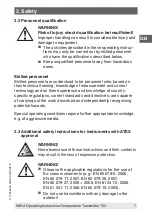
Page 7: ...urement and control technology and on their experience and knowledge of country specific regulations current standards and directives are capable of carrying out the work described and independently recognising potential hazards Special operating conditions require further appropriate knowledge e g of aggressive media 2 3 Additional safety instructions for instruments with ATEX approval WARNING No...

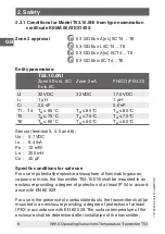
Page 8: ... Ta 75 C Ta 75 C Ta 75 C T6 Ta 60 C Ta 60 C Ta 60 C Sensor terminal 3 4 5 and 6 Uo 5 7 VDC Io 8 4 mA Po 12 mW Lo 200 mH Co 40 µF Specific conditions for safe use For use in potentially explosive atmosphere of flammable gasses vapours or mists the transmitter T53 10 0NI shall be mounted in an enclosure providing a degree of protection of at least IP 54 in accord ance with EN 60 529 For use in the p...

Page 9: ...on certificate KEMA 06ATEX148 I S approval KEMA 06ATEX0148 II 1 G Ex ia IIC T4 T6 or II 2 1 G Ex ib ia IIC T4 T6 II 1 D Ex iaD Applicable in zone 0 1 20 or 21 I S data Signal output supply terminal 1 to 2 Max ambient temperature depends on the Po of the connected barrier Sensor terminal 3 4 5 and 6 Uo 5 7 VDC Io 8 4 mA Po 12 mW Lo 200 mH Co 40 µF The effective internal capacitance and the effectiv...

Page 10: ...C Ta 45 C T53 10 0IS Class I Zone 1 Ex ib IIC FISCO Po 0 84 W FISCO systems Ui 30 VDC 17 5 VDC li 250 mA DC Pi 5 32 W Li 1 µH 1 µH Ci 2 0 nF 2 0 nF T1 T4 Ta 85 C Ta 85 C T5 Ta 75 C Ta 75 C T6 Ta 60 C Ta 60 C Installation instructions The sensor circuit is not infallibly galvanically isolated from the Field bus input circuit However the galvanic isolation between the circuits is capable of withstan...

Page 11: ...9 that is suitable for the applica tion and is correctly installed Cable entries and blanking elements shall be used that are suitable for the application and correctly installed For an ambient temperature 60 C heat resistant cables shall be used with a rating of at least 20 K above the ambient temperature The surface temperature of the enclosure is equal to the ambient temperature plus 20 K for a...

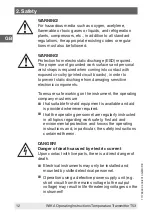
Page 12: ... sensitive electronic components To ensure safe working on the instrument the operating company must ensure that suitable first aid equipment is available and aid is provided whenever required that the operating personnel are regularly instructed in all topics regarding work safety first aid and environmental protection and knows the operating instructions and in particular the safety instructions...

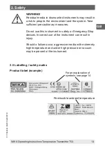
Page 13: ... may result in a risk to people the environment and the system Take sufficient precautionary measures Do not use this instrument in safety or Emergency Stop devices Incorrect use of the instrument can result in injury Should a failure occur aggressive media with extremely high temperature and under high pressure or vacuum may be present at the instrument 2 5 Labelling safety marks Product label ex...

Page 14: ...uirements of the European Directive 94 9 EC ATEX on explosion protection FM Factory Mutual The instrument was inspected and certified by FM Approvals Instruments bearing this mark comply with the applicable US standards on safety including explosion protection NEPSI National Supervision and Inspection Center for Explosion Protection and Safety of Instrumentation The instrument was inspected and ce...

Page 15: ...ation 2 100 Hz 4 g DIN IEC 68 2 6 Case material Plastic PBT glass fibre reinforced Ingress protection Case Terminal IP 68 per IEC 529 EN 60 529 IP 00 per IEC 529 EN 60 529 For further specifications see WIKA Data Sheet TE 53 01 and the order documentation Further important safety instructions for the operation in potentially explosive atmospheres can be found in chapter 2 3 Additional safety instr...

Page 16: ... FOUNDATION Fieldbus ITK version 4 61 PROFIBUS PA version 3 0 Automatic switch between protocols FISCO certified Polarity independent bus connection PROFIBUS PA function blocks 2 analogue FOUNDATION Fieldbus function blocks 2 analogue and 1 PID FOUNDATION Fieldbus capability Basic or LAS The simulation mode function for FOUNDATION Fieldbus can be activated by way of a magnet only Temperature Trans...

Page 17: ...Direct sunlight or proximity to hot objects Mechanical vibration mechanical shock putting it down hard Soot vapour dust and corrosive gases Store the instrument in its original packaging in a location that fulfills the conditions listed above If the original packaging is not available package and store the instrument as described below 1 Wrap the instrument in an antistatic plastic film 2 Place th...

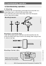
Page 18: ... Model T53 10 transmitters are designed to be mounted on a measuring insert in a Form B DIN connection head The connection wires of the measuring insert must be approx 50 mm long and insulated 6 Commissioning operation Mounting in connection head Insert the measuring insert with the mounted transmitter into the protective sheath and secure into the connecting head using screws in pressure springs ...

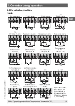
Page 19: ...ections Potentiometer 3 wire Potentiometer cable compensation 2 Potentiometer 3 wire Pt100 2 wire Pt100 3 wire Pt100 4 wire 2 x Pt100 2 wire Resistance 2 wire Resistance 3 wire Resistance 4 wire 2 x Pt100 2 3 wire 2 x Resistance 2 3 wire Thermocouple internal CJC Thermocouple external CJC Thermocouple 3 wire external CJC 2 x Thermocouple internal CJC 2 x Thermocouple 2 wire CJC 2 x mV mV 6 Commiss...

Page 20: ...48 04 03 2010 GB D F E 20 WIKA Operating Instructions Temperature Transmitter T53 Output Bus termination Bus connection Segment coupler Segment coupler PA Bus connection 6 Commissioning operation Bus termination ...

Page 21: ...C Analogue to Digital converter Transducer block Input 1 Input 2 Difference Average Redundancy Terminal temperature Engineering units Diagnostics Table linearisation Polynominal linearisation Process calibration EEPROM Complete configuration Correktion coefficients Factory settings Automatic communication switch Function blocks AI1 AI2 PID LAS Foundation fieldbus Protocol Ex circuit 3 4 5 6 Functi...

Page 22: ...Transmitter T53 6 4 Bus installation T53 10 0NI T53 10 0IS T53 10 0NI T53 10 0NI T53 10 0IS T53 10 0IS Segment coupler Power supply Safe area Segment coupler Ex Power supply To additional segment couplers Hazardous area Bus termination Bus termination 6 Commissioning operation ...

Page 23: ...fficient precautionary measures 8 1 Return WARNING Absolutely observe when shipping the instrument All instruments delivered to WIKA must be free from any kind of hazardous substances acids bases solutions etc When returning the instrument use the original packaging or a suitable transport package To avoid damage 1 Wrap the instrument in an antistatic plastic film 2 Place the instrument along with...

Page 24: ... instrument The return form is available on the internet www wika de Service Return 8 2 Disposal Incorrect disposal can put the environment at risk Dispose of instrument components and packaging materials in an environmentally compatible way and in accordance with the country specific waste disposal regulations 8 Return and disposal ...

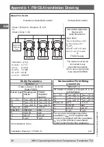
Page 25: ...or Uo Vmax or Ui lsc or lo lmax or li Po Pi Ca or Co Ci Ccable La or Lo Li or Lcable Class I Division 1 Groups A B C D or Class I Zone 0 IIC Hazardous classified Location Terminal 1 2 Class I Zone 0 Ex ia IIC Entity FISCO IS Class I Division 1 Group A B C D Entity FISCO Barrier type Linear barrier Trapezoid barrier Suitable for FISCO systems Suitable for FISCO systems T1 T4 Ta 85 C Ta 75 C Ta 85 C...

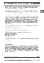
Page 26: ...dous classified Location Entity Parameters Terminal 1 2 Class I Zone 1 Ex ib IIC Entity FISCO Barrier type Rectangular barrier FISCO Segment coupler T1 T4 Ta 85 C Ta 85 C T5 Ta 75 C Ta 75 C T6 Ta 60 C Ta 60 C Vmax Ui 30 V 17 5 V lmax or li 250 mA any Pi 5 32 W any Ci 2 0 nF 2 0 nF Li 1 µH 1 µH See Installation notes Installation Drawing 11175631 01 2 6 Nonincendive Field Wiring parameters Terminal...

Page 27: ... 40 µF La or Lo 200 mH Terminal 1 2 Ci 2 0 nF Li 1µH The device must not be connected to any associated apparatus which uses or generates more than 250 VRMS 32 V Class 2 Power Supply Unclassified Location Class I Division 2 Groups A B C D or Class I Zone 2 IIC Hazardous classified Location T1 T4 40 C Ta 85 C T5 40 C Ta 75 C T6 40 C Ta 60 C See Installation notes Installation Drawing 11175631 01 3 ...

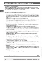
Page 28: ... Io or ISC or It and the power Po which can be delivered by the barrier The sum of the maximum unprotected capacitance Ci for each intrinsically device and the interconnecting wiring must be less than the capacitance Ca which can be safely connected to the barrier The sum of the maximum unprotected inductance Li for each intrinsically device and the interconnecting wiring must be less than the ind...

Page 29: ... that the intrinsically safe Fieldbus circuit remains passive The cable used to interconnect the devices needs to comply with the following parameters Loop resistance R 15 150 Km Inductance per unit length L 0 4 1 mH km Capacitance per unit length C 80 200 nF km C C line line 0 5 C line screen if both lines are floating or C C line line C line screen if the screen is connected to one line Length o...

Page 30: ...fe Installation should be in accordance with ANSI ISA RP12 6 01 except chapter 5 for FISCO Installations Installation of Intrinsically Safe Systems for Hazardous Classified Locations and the National Electrical Code ANSI NFPA 70 Sections 504 and 505 5 The configuration of associated Apparatus must be FM Approvals or CSA Approved under the associated concept 6 Associated Apparatus manufacturer s in...

Page 31: ...GB 11178648 04 03 2010 GB D F E WIKA Operating Instructions Temperature Transmitter T53 31 Appendix 2 EC Declaration of conformity ...

Page 32: ...GB 11178648 04 03 2010 GB D F E 32 WIKA Operating Instructions Temperature Transmitter T53 ...

Page 33: ...3 1 Allgemeines 34 2 Sicherheit 36 3 Technische Daten 45 4 Aufbau und Funktion 46 5 Transport Verpackung und Lagerung 47 6 Inbetriebnahme Betrieb 48 7 Wartung 53 8 Rücksendung und Entsorgung 53 Anlage 1 FM CSA Installation Drawing 25 Anlage 2 EG Konformitätserklärung 31 Inhalt Inhalt ...

Page 34: ...svorschriften und allgemeinen Sicherheitsbe stimmungen einhalten Die Betriebsanleitung ist Produktbestandteil und muss in un mittelbarer Nähe des Gerätes für das Fachpersonal jederzeit zugänglich aufbewahrt werden Das Fachpersonal muss die Betriebsanleitung vor Beginn aller Arbeiten sorgfältig durchgelesen und verstanden haben Die Haftung des Herstellers erlischt bei Schäden durch bestim mungswidr...

Page 35: ...bt nützliche Tipps und Empfehlungen sowie Informationen für einen effizienten und störungsfreien Betrieb hervor GEFAHR kennzeichnet Gefährdungen durch elektrischen Strom Bei Nichtbeachtung der Sicherheitshinweise besteht die Gefahr schwerer oder tödlicher Verletzungen WARNUNG weist auf eine möglicherweise gefährliche Situation im explosionsgefährdeten Bereich hin die zum Tod oder zu schweren Verle...

Page 36: ...s und Sensorgeber sowie Potentiometermessung Das Gerät ist ausschließlich für den hier beschriebenen bestim mungsgemäßen Verwendungszweck konzipiert und konstruiert und darf nur dementsprechend verwendet werden Die technischen Spezifikationen in dieser Betriebsanleitung sind einzuhalten Eine unsachgemäße Handhabung oder ein Betreiben des Gerätes außerhalb der technischen Spezifikationen macht die ...

Page 37: ...Regelungstechnik und seiner Erfahrun gen sowie Kenntnis der landesspezifischen Vorschriften geltenden Normen und Richtlinien in der Lage die beschriebenen Arbeiten auszuführen und mögliche Gefahren selbstständig zu erkennen Spezielle Einsatzbedingungen verlangen weiteres entsprechendes Wissen z B über aggressive Medien 2 3 Zusätzliche Sicherheitshinweise für Geräte mit ATEX Zulassung WARNUNG Die N...

Page 38: ...a 75 C T6 Ta 60 C Ta 60 C Ta 60 C Anschluss des Sensors Klemmen 3 4 5 und 6 Uo 5 7 VDC Io 8 4 mA Po 12 mW Lo 200 mH Co 40 µF Besondere Bedingungen für den sicheren Betrieb Für den Einsatz in Bereichen die möglicherweise durch brennbare Gase Dämpfe oder Nebel gefährdet sind muss der Transmitter T53 10 0NI in ein Gehäuse eingebaut werden das mindestens der Schutzart IP 54 gemäß EN 60 529 entspricht ...

Page 39: ...bescheinigung KEMA 06ATEX148 Ex Zulassung KEMA 06ATEX0148 X II 1 G Ex ia IIC T4 T6 oder II 2 1 G Ex ib ia IIC T4 T6 II 1 D Ex iaD Betrieb in Zone 0 1 2 20 21 oder 22 Ex Daten Signalausgang Hilfsenergie Klemmen 1 bis 2 Die maximale Umgebungstemperatur hängt von der Leistung Po der angeschlossenen Sperre ab Anschluss des Sensors Klemmen 3 4 5 und 6 Uo 5 7 VDC Io 8 4 mA Po 12 mW Lo 200 mH Co 40 µF Di...

Page 40: ...0 0IS Class I Zone 1 Ex ib IIC FISCO Po 0 84 W FISCO systems Ui 30 VDC 17 5 VDC li 250 mA DC Pi 5 32 W Li 1 µH 1 µH Ci 2 0 nF 2 0 nF T1 T4 Ta 85 C Ta 85 C T5 Ta 75 C Ta 55 C T6 Ta 60 C Ta 60 C Montagehinweise Die galvanische Trennung zwischen dem Sensorstromkreis und der Eingangsbeschaltung ist nicht unfehlbar Allerdings ist die galvani sche Trennung zwischen den Kreisen so ausgelegt dass diese ei...

Page 41: ...den dementsprechenden Einsatz zugelassen und korrekt installiert ist Es dürfen nur Kabeleinführungen und Abdeckungen eingesetzt werden welche für die jeweilige Anwendung zugelassen und die richtig installiert sind Bei einer Umgebungstemperatur 60 C müssen hitzebeständige Leitungen eingesetzt werden die für eine mindestens 20 K höhere Umgebungstemperatur zugelassen sind Die Oberflächentemperatur de...

Page 42: ...tische Entladung zu vermeiden Für ein sicheres Arbeiten am Gerät muss der Betreiber sicherstellen dass eine entsprechende Erste Hilfe Ausrüstung vorhanden ist und bei Bedarf jederzeit Hilfe zur Stelle ist dass das Bedienpersonal regelmäßig in allen zutref fenden Fragen von Arbeitssicherheit Erste Hilfe und Umweltschutz unterwiesen wird sowie die Betriebs anleitung und insbesondere die darin enthal...

Page 43: ...tsmaßnahmen ergreifen Dieses Gerät nicht in Sicherheits oder in Not Aus Einrichtungen benutzen Fehlerhafte Anwendungen des Gerätes können zu Verletzungen führen Am Gerät können im Fehlerfall aggressive Medien mit extremer Temperatur und unter hohem Druck oder Vakuum anliegen 2 5 Beschilderung Sicherheitskennzeichnungen Typenschild Beispiel 2 Sicherheit zulässige Umgebungstemperatur Symbolerklärung...

Page 44: ...europäischen Richtlinie 94 9 EG ATEX zum Explosionsschutz FM Factory Mutual Das Gerät wurde von FM Approvals geprüft und zertifi ziert Geräte mit dieser Kennzeichnung stimmen überein mit den anwendbaren US amerikanischen Normen zur Sicherheit einschließlich Explosionsschutz NEPSI National Supervision and Inspection Center for Explosion Protection and Safety of Instrumentation Das Gerät wurde von N...

Page 45: ...ung Vibration 2 100 Hz 4 g DIN IEC 68 2 6 Gehäusematerial Kunststoff PBT glasfaserverstärkt Schutzart Gehäuse Klemmen IP 68 nach IEC 529 EN 60 529 IP 00 nach IEC 529 EN 60 529 Weitere technische Daten siehe WIKA Datenblatt TE 53 01 und Bestellunterlagen Weitere wichtige Sicherheitshinweise für den Betrieb in explosionsgefährdeten Bereichen siehe Kapitel 2 3 Zusätzliche Sicherheitshinweise für Gerä...

Page 46: ...en FOUNDATION Fieldbus ITK Version 4 61 PROFIBUS PA Version 3 0 Automatische Umschaltung zwischen den Protokollen FISCO zertifiziert Polaritätsunabhängige Busanschluss PROFIBUS PA Funktionsblöcke 2 Analoge FOUNDATION Fieldbus Funktionsblöcke 2 Analoge und 1 PID FOUNDATION Fieldbus Funktionalität Basic oder LAS Der Simulationsmodus kann bei FOUNDATION Fieldbus nur mittels eines Magneten aktiviert w...

Page 47: ...nenlicht oder Nähe zu heißen Gegenständen Mechanische Vibration mechanischer Schock hartes Aufstellen Ruß Dampf Staub und korrosive Gase Das Gerät in der Originalverpackung an einem Ort der die oben gelisteten Bedingungen erfüllt lagern Wenn die Originalverpackung nicht vorhanden ist dann das Gerät wie folgt verpacken und lagern 1 Das Gerät in eine antistatische Plastikfolie einhüllen 2 Das Gerät ...

Page 48: ...f Messeinsatz mit montiertem Transmitter in die Schutzarmatur einste cken und im Anschlusskopf mit Schrauben federnd befestigen Montage von Fühlerleitungen 6 Inbetriebnahme Betrieb 6 1 Montage Die Transmitter Typ T53 10 sind vorgesehen zur Montage auf einem Messeinsatz im DIN Anschlusskopf der Form B Die Anschluss drähte des Messeinsatzes müssen ca 50 mm lang und isoliert ausgeführt sein 6 Inbetri...

Page 49: ...entiometer 3 Leiter Potentiometer Kabelkompensation 2 Potentiometer 3 Leiter Pt100 2 Leiter Pt100 3 Leiter Pt100 4 Leiter 2 x Pt100 2 Leiter Widerstand 2 Leiter Widerstand 3 Leiter Widerstand 4 Leiter 2 x Pt100 2 3 Leiter 2 x Widerstand 2 3 Leiter Thermoelement interne CJC Thermoelement externe CJC Thermoelement 3 Leiter externe CJC 2 x Thermoelement interne CJC 2 x Thermoelement 2 Leiter CJC 2 x ...

Page 50: ...1178648 04 03 2010 GB D F E 50 WIKA Betriebsanleitung Temperatur Transmitter T53 Ausgang Busabschluss Bus Verbindung Segment koppler Segment koppler PA Bus Verbindung Busabschluss 6 Inbetriebnahme Betrieb ...

Page 51: ...C A D Wandler Transducer Block Eingang 1 Eingang 2 Differenz Mittelwert Redundanz Klemmentemperatur Engineering Einheiten Diagnosefunktionen Tabellen Linearisierung Polynom Linearisierung Prozesskalibrierung EEPROM Komplette Konfiguration Korrekturkoeffizienten Werkseinstellungen Automatische Busumschaltung Funktions blöcke AI1 AI2 PID LAS Foundation fieldbus Protokoll Ex Stromkreis 3 4 5 6 Funkti...

Page 52: ...3 6 4 Businstallation T53 10 0NI T53 10 0IS T53 10 0NI T53 10 0NI T53 10 0IS T53 10 0IS Segmentkoppler Versorgungsspannung Sicherer Bereich Segmentkoppler Ex Versorgungsspannung An zusätzliche Segmentkoppler Ex gefährdeter Bereich Bus abschluss Bus abschluss 6 Inbetriebnahme Betrieb ...

Page 53: ...d zu ergreifen 8 1 Rücksendung WARNUNG Beim Versand des Gerätes unbedingt beachten Alle an WIKA gelieferten Geräte müssen frei von Gefahrstoffen Säuren Laugen Lösungen etc sein Zur Rücksendung des Gerätes die Originalverpackung oder eine geeignete Transportverpackung verwenden Um Schäden zu vermeiden 1 Das Gerät in eine antistatische Plastikfolie einhüllen 2 Das Gerät mit dem Dämmmaterial in der V...

Page 54: ...dung 8 2 Entsorgung Durch falsche Entsorgung können Gefahren für die Umwelt entstehen Gerätekomponenten und Verpackungsmaterialien entsprechend den landesspezifischen Abfallbehandlungs und Entsorgungsvorschriften umweltgerecht entsorgen Anlage 1 FM CSA Installation Drawing siehe Seite 25 Anlage 2 EG Konformitätserklärung siehe Seite 31 8 Rücksendung und Entsorgung ...

Page 55: ...Transport emballage et stockage 69 6 Mise en service exploitation 71 7 Entretien 76 8 Retour et mise au rebut 76 Annexe 1 FM CSA Installation Drawing 25 Annexe 2 Déclaration de conformité CE 78 F WIKA Mode d emploi Transmetteur de température T53 11178648 04 03 2010 GB D F E 55 Sommaire Sommaire ...

Page 56: ...le domaine d application de l appareil Le mode d emploi fait partie de l appareil et doit être conservé à proximité immédiate de l appareil et accessible à tout moment pour le personnel qualifié Le personnel qualifié doit avant de commencer toute opération avoir lu soigneusement et compris le mode d emploi La responsabilité du fabricant n est pas engagée en cas de dommages provoqués par une utilis...

Page 57: ...tion met en exergue les conseils et recommandations utiles de même que les informations permettant d assurer un fonctionnement efficace et normal DANGER indique les dangers liés au courant électrique Danger de blessures graves ou mortelles en cas de non respect des consignes de sécurité AVERTISSEMENT indique une situation en zone explosive présentant des risques susceptibles de provoquer la mort o...

Page 58: ...s de résistance et de tension ainsi que mesure de potentiomètre L appareil est conçu et construit exclusivement pour une utilisation conforme à lusage prévu décrit ici et ne doit être utilisé qu en consé quence Les spécifications techniques mentionnées dans ce mode d emploi doivent être respectées En cas d utilisation inadéquate ou de fonctionnement de l appareil en dehors des spécifications techn...

Page 59: ...onnel qualifié est en raison de sa formation spécialisée de ses connaissances dans le domaine de la technique de mesure et de régulation et de ses expériences de même que de sa connais sance des prescriptions nationales des normes et directives en vigueur en mesure d effectuer les travaux décrits et de reconnaître automatiquement les dangers potentiels Les conditions d utilisation spéciales exigen...

Page 60: ...s dommages externes 2 3 1 Conditions pour le type T53 10 0NI selon attestation d examen CE de type KEMA 06ATEX149 Homologation zone 2 II 3 GD Ex nA nL IIC T4 T6 II 3 GD Ex nL IIC T4 T6 II 3 GD Ex nA ic IIC T4 T6 II 3 GD Ex ic IIC T4 T6 Paramètres T53 10 0NI Zone 2 Ex nL IIC Ex ic IIC Zone 2 nA FNICO FISCO Ui 32 VDC 32 VDC 17 5 VDC Li 1 µH 1 µH Ci 2 0 nF 2 0 nF 2 0 nF T1 T4 Ta 85 C Ta 85 C Ta 85 C ...

Page 61: ... EN 60 529 La température de la surface du boîtier doit être déterminée après le montage du transmetteur Pour une température ambiante 60 C il faut utiliser des câbles résistant à la chaleur lesquels doivent être agréés pour une température ambiante supérieure d au moins 20 K 2 3 2 Conditions pour le type T53 10 0IS selon attestation d examen CE de type KEMA 06ATEX148 Homologation Ex KEMA 06ATEX01...

Page 62: ...Ci 2 0 nF 2 0 nF 2 0 nF 2 0 nF T1 T4 Ta 85 C Ta 75 C Ta 85 C Ta 85 C T5 Ta 70 C Ta 65 C Ta 60 C Ta 60 C T6 Ta 60 C Ta 45 C Ta 45 C Ta 45 C T53 10 0IS Class I Zone 1 Ex ib IIC FISCO Po 0 84 W FISCO systems Ui 30 VDC 17 5 VDC li 250 mA DC Pi 5 32 W Li 1 µH 1 µH Ci 2 0 nF 2 0 nF T1 T4 Ta 85 C Ta 85 C T5 Ta 75 C Ta 55 C T6 Ta 60 C Ta 60 C Instructions de montage L isolation galvanique entre le circuit...

Page 63: ...électrostatique doit être évitée Pour une utilisation dans une atmosphère potentiellement explosive avec de la poussière les indications suivantes sont valables Le transmetteur doit être monté dans une tête métallique forme B selon DIN 43 729 qui dispose d un indice de protection IP 6X au moins selon EN 60 529 qui est homologuée pour l utilisation correspondante et correctement installée On doit s...

Page 64: ...de sécurité complémentaires pour les appareils avec homologation ATEX AVERTISSEMENT Dans le cas de fluides de mesure dangereux comme notamment l oxygène l acétylène des substances combustibles ou toxiques ainsi que dans le cas d installations de réfrigération de compresseurs etc les directives appropriées existantes doivent être obser vées en plus de l ensemble des règles générales AVERTISSEMENT P...

Page 65: ... en cas de contact avec les pièces sous tension Le montage de l appareil électrique ne doit être effectué que par un électricien qualifié En cas d utilisation avec un appareil d alimentation défectueux p ex court circuit entre la tension du secteur et la tension de sortie des tensions présentant un danger de mort peuvent apparaître sur l appareil AVERTISSEMENT Les restes de fluides se trouvant dan...

Page 66: ... par CSA Internatio nal Les appareils avec ce marquage sont conformes aux normes canadiennes de sécurité protection contre les explosions incluse applicables CE Communauté Européenne Les appareils avec ce marquage sont conformes aux directives européennes pertinentes ATEX Directive européenne sur les appareils destinés à être utilisés en atmosphère explosible Atmosphère AT Explosion Ex Les apparei...

Page 67: ...strumentation L appareil a été contrôlé et certifié par NEPSI Les appareils avec ce marquage sont conformes aux normes chinoises de sécurité protection contre les explosions incluse applicables INMETRO National Institute of Metrology Standardization and Industrial Quality L appareil a été contrôlé et certifié par INMETRO Les appareils avec ce marquage sont conformes aux normes brésiliennes de sécu...

Page 68: ...mmande Pour d autres consignes de sécurité importantes pour exploitation en zone potentiellement explosive voir chapitre 2 3 Consignes de sécurité complémentaires pour les appareils avec homologation ATEX 4 Conception et fonction 4 1 Description Le T53 10 transforme une valeur de résistance ou de tension en une valeur de mesure proportionnelle numérique La valeur de mesure numérique sera ultérieur...

Page 69: ... prévu pour le montage dans une tête de raccordement standard d une sonde de température 4 2 Volume de livraison Comparer le détail de la livraison avec le bordereau de livraison 5 Transport emballage et stockage 5 1 Transport Vérifier s il existe des dégâts sur l appareil liés au transport Communiquer immédiatement les dégâts constatés 5 2 Emballage N enlever l emballage qu avant le montage Conse...

Page 70: ... est pas disponible emballer et stocker l appareil comme suit 1 Emballer l appareil dans une feuille de plastique antistatique 2 Placer l appareil avec le matériau isolant dans l emballage 3 En cas d entreposage long plus de 30 jours mettre également un sachet absorbeur d humidité dans l emballage AVERTISSEMENT Enlever tous les restes de fluides adhérents avant l entreposage de l appareil après le...

Page 71: ...tage sur sonde dans une tête de raccordement de forme B selon DIN Les fils de branchement de la sonde doivent avoir une longueur d environ 50 mm et être isolés 6 Mise en service exploitation 11198991 01B Exemple de montage 11198991 01A Montage dans la tête de raccordement Introduire la sonde avec le transmetteur monté dans la gaine de protection et la fixer sur ressort dans la tête de raccordement...

Page 72: ...électriques potentiomètre 3 fils potentiomètre compensation de câble 2 potentiomètre 3 fils Pt100 2 fils Pt100 3 fils Pt100 4 fils 2 x Pt100 2 fils résistance 2 fils résistance 3 fils résistance 4 fils 2 x Pt100 2 3 fils 2 x résistance 2 3 fils thermocouple CJC interne thermocouple CJC externe thermocouple 3 fils CJC externe 2 x thermocouple CJC interne 2 x thermocouple 2 fils CJC 2 x mV mV 6 Mise...

Page 73: ...de d emploi Transmetteur de température T53 11178648 04 03 2010 GB D F E 73 Sortie Branchement bus liaison bus coupleur à segment coupleur à segment PA liaison bus 6 Mise en service exploitation Branchement bus ...

Page 74: ...ertisseur Entrée 1 Entrée 2 Différence Valeur moyenne Redondance Température des bornes Unités d engineering Fonctions de diagnostic Tableaux de linéarisation Linéarisation des polynômes Calibration de processus EEPROM Configuration complète Coefficients de correction Réglages d usine Commutation de bus automatique Blocs de fonctions AI1 AI2 PID LAS Foundation fieldbus Protocole Circuit courant Ex...

Page 75: ...3 2010 GB D F E 75 T53 10 0NI T53 10 0IS T53 10 0NI T53 10 0NI T53 10 0IS T53 10 0IS Coupleurs à segment Alimentation Zone sécurisée Coupleurs à segment Ex Alimentation pour des coupleurs à segment supplémentaires Zone explosive Branchement bus Branchement bus 6 Mise en service exploitation ...

Page 76: ...res de sécurité suffisantes 8 1 Retour AVERTISSEMENT En cas d envoi de l appareil il faut respecter impérative ment ceci ci Tous les appareils livrés à WIKA doivent être exempts de toutes substances dangereuses acides solutions alcalines solutions etc Pour retourner l appareil utiliser l emballage original ou un emballage adapté pour le transport Pour éviter des dommages 1 Emballer l appareil dans...

Page 77: ...e Service Retour 8 2 Mise au rebut Une mise au rebut inadéquate peut entraîner des dangers pour l environnement Éliminer les composants des appareils et les matériaux d emballage conformément aux prescriptions nationales pour le traitement et l élimination des déchets et aux lois de protection de l environnement en vigueur Annexe 1 FM CSA Installation Drawing voir page 25 8 Retour et mise au rebut...

Page 78: ...F 11178648 04 03 2010 GB D F E 78 WIKA Mode d emploi Transmetteur de température T53 Annexe 2 Déclaration de conformité CE ...

Page 79: ...laje y almacenamiento 93 6 Puesta en servicio funcionamiento 94 7 Mantenimiento 99 8 Devolución y eliminación 99 Anexo 1 FM CSA Installation Drawing 25 Anexo 2 Declaración CE de conformidad 78 E WIKA Manual de Instrucciones Transmisor de temperatura T53 11178648 04 03 2010 GB D F E 79 Contenido Contenido ...

Page 80: ...ón del instrumento El manual de instrucciones es una parte integrante del instrumento y debe guardarse en la proximidad del mismo para que el personal especializado pueda consultarlo en cualquier momento El personal especializado debe haber leído y entendido el manual de instrucciones antes de comenzar cualquier trabajo El fabricante queda exento de cualquier responsabilidad en caso de daños causa...

Page 81: ...rmación marca consejos y recomendaciones útiles así como informaciones para una utilización eficaz y libre de fallos PELIGRO indica riesgos causados por corriente eléctrica Hay un riesgo de lesiones graves o mortales si no se observan estas indicaciones de seguridad ADVERTENCIA indica una situación probablemente peligrosa en una atmósfera potencialmente explosiva que causa la muerte o lesiones gra...

Page 82: ... termo pares TC transmisores de resistencia y tensión así como para medición de potenciómetro El instrumento ha sido diseñado y construido únicamente para la finalidad aquí descrita y debe utilizarse en conformidad a la misma Cumplir las especificaciones técnicas de este manual de instruc ciones Un manejo no apropiado o una utilización del instrumento no conforme a las especificaciones técnicas re...

Page 83: ...specializado con la consiguiente cualificación Mantener alejado a personal no cualificado de las zonas peligrosas Personal especializado Debido a su formación profesional a sus conocimientos de la técnica de regulación y medición así como a su experiencia y su conocimiento de las normativas normas y directivas vigentes en el país de utilización el personal especializado es capaz de ejecutar los tr...

Page 84: ... ej EN 60 079 0 2006 EN 60 079 11 2007 EN 60 079 26 2007 EN 60 079 27 2006 2008 EN 61 241 0 2006 EN 61 241 11 2006 EN 60 079 15 2005 No utilizar los transmisores cuyo exterior está dañado 2 3 1 Condiciones para el modelo T53 10 0NI del certificado CE de Modelo KEMA 06ATEX149 Homologación Ex II 3 GD Ex nA nL IIC T4 T6 II 3 GD Ex nL IIC T4 T6 II 3 GD Ex nA ic IIC T4 T6 II 3 GD Ex ic IIC T4 T6 Datos ...

Page 85: ...nsmisor debe integrarse en una caja que corresponda por lo menos al tipo de protección IP 6X según EN 60 529 La temperatura de superficie de la caja debe determinarse tras la instalación del transmisor Con una temperatura ambiental 60 C se deben utilizar cables termorresistentes autorizados para una temperatura ambiental de al menos 20 K más elevada 2 3 2 Condiciones para el modelo T53 10 0IS del ...

Page 86: ...IC o Ex iaD FISCO Po 0 84 W Po 1 3 W FISCO systems FISCO systems Ui 30 VDC 30 VDC 17 5 VDC 15 VDC li 120 mA DC 300 mA DC 250 mA DC Pi 0 84 W 1 3 W 2 0 W Li 1 µH 1 µH 1 µH 1 µH Ci 2 0 nF 2 0 nF 2 0 nF 2 0 nF T1 T4 Ta 85 C Ta 75 C Ta 85 C Ta 85 C T5 Ta 70 C Ta 65 C Ta 60 C Ta 60 C T6 Ta 60 C Ta 45 C Ta 45 C Ta 45 C T53 10 0IS Class I Zone 1 Ex ib IIC FISCO Po 0 84 W FISCO systems Ui 30 VDC 17 5 VDC ...

Page 87: ...e averías puedan excluirse fuentes de encen dido causadas por chispas debidos a choques o fricción Si la caja es de materiales no metálicos hay que evitar cargas electrostáticas Para la utilización en atmósferas potencialmente explosivas por mezclas de polvo aire se aplican las siguientes indicaciones El transmisor debe estar integrado en un cabezal de metal forma B según DIN 43 729 que correspond...

Page 88: ...es de refrigeración compresores etc deben observarse en cada caso además de todas las reglas generales las disposiciones pertinentes ADVERTENCIA Es imprescindible una protección de descarga electrostática ESD La utilización apropiada de superficies de trabajo puestas a tierra y de pulseras individuales es imprescindible para trabajos en circuitos abiertos placas de circuitos impresos para poder ev...

Page 89: ...pueden generarse tensiones letales en el instrumento ADVERTENCIA Restos de medios en instrumentos desmontados pueden crear riesgos para personas medio ambiente e instalación Tomar adecuadas medidas de precaución No utilizar este instrumento en sistemas de seguridad o de parada de emergencia Una utilización incorrecta del instrumento puede causar lesiones En caso de fallo es posible que haya medios...

Page 90: ... la prevención de explosiones FM Factory Mutual Este instrumento ha sido comprobado y certificado por FM Approvals Los instrumentos con este marcado están conformes a las normas aplicables de los EE UU relativas a la seguridad incluidas las de la protección contra explosiones NEPSI National Supervision and Inspection Center for Explosion Protection and Safety of Instrumentation Este instrumento ha...

Page 91: ...2 6 Material del envolvente Plástico PBTP reforzado con fibra de vidrio Tipo de protección Caja Bornes IP 68 según IEC 529 EN 60 529 IP 00 según IEC 529 EN 60 529 Para más datos técnicos véase la hoja técnica de WIKA TE 53 01 y la documentación de pedido Otras importantes indicaciones de seguridad sobre el funcionamiento en una atmósfera potencialmente explosiva véase el capítulo 2 3 Instrucciones...

Page 92: ...ocoles FOUNDATION Fieldbus ITK versión 4 61 PROFIBUS PA versión 3 0 Conmutación automática entre los protocoles FISCO certificado Conexión de bus independiente de la polaridad PROFIBUS PA bloques de función 2 analógicos FOUNDATION Fieldbus bloques de función 2 analógicos y 1 PID FOUNDATION Fieldbus funcionalidad Basic o LAS El modo de simulación para FOUNDATION Fieldbus puede activarse sólo median...

Page 93: ...lo siguiente Luz solar directa o proximidad a objetos calientes Vibración mecánica impacto mecánico colocación brusca Hollín vapor polvo y gases corrosivos Almacenar el instrumento en su embalaje original en un lugar que cumple las condiciones arriba mencionadas Si no se dispone del embalaje original empaquetar y almacenar el instrumento como sigue 1 Envolver el instrumento en una lámina de plásti...

Page 94: ... transmisor montado en la funda protectora y fijarlo en el cabezal utilizando tornillos con resorte de presión Montaje de cables del sensor 6 Puesta en servicio funcionamiento 6 1 Montaje Los transmisores Modelo T53 10 están previstos para su montaje en un cabezal de forma DIN B con una unidad extraíble Los hilos de la conexión de la unidad extraíble deben tener una longitud de aprox 50 mm y deben...

Page 95: ...ctricas Potenciómetro 3 hilos Potenciómetro compensación de cable 2 potenciómetros 3 hilos Pt100 2 hilos Pt100 3 hilos Pt100 4 hilos 2 x Pt100 2 hilos Resistencia 2 hilos Resistencia 3 hilos Resistencia 4 hilos 2 x Pt100 2 3 hilos 2 x resistencia 2 3 hilos Termopar CJC interno Termopar CJC externo Termopar 3 hilos CJC externo 2 x termopar CJC interno 2 x termopar 2 hilos CJC 2 x mV mV 6 Puesta en ...

Page 96: ...D F E 96 WIKA Manual de Instrucciones Transmisor de temperatura T53 Salida Conexión de bus Terminación de bus Acoplador de segmento PA Terminación de bus 6 Puesta en servicio funcionamiento Acoplador de segmento Conexión de bus ...

Page 97: ...o A D Convertidor Transducer Block Entrada 1 Entrada 2 Diferencia Valor medio Redundancia Temperatura del terminal Unidades ingeniería Diagnósticos Linealización de tabla Linealización polinomio Calibración de proceso EEPROM Configuración completa Coeficiente de corrección Ajustes de fábrica Conmutación de bus automática Bloques de función AI1 AI2 PID LAS Foundation fieldbus Protocolo Circuito Ex ...

Page 98: ...T53 10 0NI T53 10 0IS T53 10 0NI T53 10 0NI T53 10 0IS T53 10 0IS Acoplador de segmento Tensión de alimentación Área segura Acoplador de segmento Ex Tensión de alimentación Hacia acopladores de segmento adicionales Área potencialmente explosiva Terminación de bus Terminación de bus 6 Puesta en servicio funcionamiento ...

Page 99: ...ente e instalación Tomar adecuadas medidas de precaución 8 1 Devolución ADVERTENCIA Es imprescindible observar lo siguiente para el envío del instrumento Todos los instrumentos enviados a WIKA deben estar libres de sustancias peligrosas ácidos lejías soluciones etc Utilizar el embalaje original o un embalaje adecuado para la devolución del instrumento Para evitar daños 1 Envolver el instrumento en...

Page 100: ...correcta puede provocar peligros para el medio ambiente Eliminar los componentes de los instrumentos y los materiales de embalaje conforme a los reglamentos relativos al tratamiento de residuos y eliminación vigentes en el país de utilización Anexo 1 FM CSA Installation Drawing Véase página 25 Anexo 2 Declaración CE de conformidad Véase página 78 8 Devolución y eliminación de residuos WIKA Niederl...

Reviews: