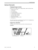
background image


Hopper Plus 120-24

Wireless Ethernet Bridge


Installation and

 Configuration Guide


Version 1.0 Rev B

08/00

Summary of Contents for Hopper Plus 120-24

Page 1: ...Hopper Plus 120 24 Wireless Ethernet Bridge Installation and Con guration Guide Version 1 0 Rev B 08 00...

Page 2: ...s Units 2 Hardware Description 3 Shipping Package Contents 3 Hopper Plus 120 24 Unit 3 Hopper Plus 120 24 Specifications 6 Installation 9 Basic Installation Steps 9 Configuring a Unit as a Base 10 Tes...

Page 3: ...k Monitor Remote Station Rank Base Station Only 38 Setting Throttling Remote Station Only 40 Radio Module Configuration 41 Setting the Station Type 42 Setting the Station Rank 43 Setting the Center Fr...

Page 4: ...Optimizing the RF Link 72 Overview 72 Working with System Gain 74 Calculating EIRP Effective Isotropically Radiated Power 75 Optimizing Antenna Gain 76 Calculating Propagation Loss 76 Working with th...

Page 5: ...work 94 Enabling the Sharing Feature on the Hard Disk Drive 97 Appendix D SNMP MIB 99 About SNMP MIB 99 Wi LAN Object Identifier Nodes 100 Using Object Identifier Nodes 101 Appendix E Technical Refere...

Page 6: ...the following regulations and or regulatory bodies RSS 210 and or RSS 139 of Industry Canada FCC Part 15 CEPT ERC Recommendations ETS 300 328 ETS 300 826 and EN 60950 Operation is subject to the foll...

Page 7: ...ted to chassis ground shall be used to reduce the radio frequency interference FCC radio frequency exposure limits may be exceeded at distances closer than 23 centimeters from the antenna of this devi...

Page 8: ...ports point to point and point to multipoint networks Contentionless polling ensures efficient access to remote data networks is self contained and easy to use Simply connect a Hopper Plus 120 24 to e...

Page 9: ...units link wired segments of the network wirelessly to the main network via the base station Remotes can limit the amount of data passed by the remote a function called throttling and they can filter...

Page 10: ...er straight through ethernet cable RJ45 crossover ethernet cable RJ45 DB9 M to DB25 F adaptor RS 232 DB9 serial cable Installation and Configuration Guide Warranty Card If any of the above items are n...

Page 11: ...with a PC Use this port to con gure test and set up the Hopper Plus AIR LED Color of LED indicates the status of the wireless link during transmit receive or listen Normal color Orange MODE LED Color...

Page 12: ...detailed pinout illustration MODE Button The mode button can be used to set the operating mode of a unit without a terminal See Setting Operating Mode with the MODE Button page 68 for information abo...

Page 13: ...ivity 83 dBm Processing Gain 10 dB Network Support Packet Format IEEE 802 3 and Ethernet II High level protocol transparent LAN Connection 10 100 BaseT autonegotiates Bridge Functionality Local Packet...

Page 14: ...RFC 1213 Management Port Functionality Supports system con guration security access control wireless LAN diagnostics and management menu driven ASCII interface via RS 232 DB 9 Environment Units must b...

Page 15: ...Description 8 Version 1 0 Rev B 08 00...

Page 16: ...om the factory con gured as remotes 4 Test the basic operation of the bridge See Testing Basic Operation page 11 for more information 5 Place the units in their eld locations and connect them to anten...

Page 17: ...to change the station type of remotes No user software is required to install a unit To con gure one unit as a base unit 1 Connect a PC to the MANGAGEMENT port to the Hopper Plus unit that will be th...

Page 18: ...ry configured as remotes Performing a Bench Test To perform a bench test of the bridge 1 Ensure that you have configured a unit as a base unit 2 Ensure that the station type of all other units is Remo...

Page 19: ...d 7 Run the Link Monitor test on the remote unit See Setting Link Monitor Remote Station Rank Base Station Only page 38 Check for RSSI below 40 and BER 0 If you have problems ensure that the unit is c...

Page 20: ...ows 4 Create some network traffic to test the bridge for example transfer a file across the bridge The WIRE LED indicates the activity See Appendix C Configuring a Simple Data Network page 93 for more...

Page 21: ...Installation 14 Version 1 0 Rev B 08 00...

Page 22: ...our keyboard keys to select view or change settings Some items in the menu simply display information while others ask you to enter data or make a selection from a list Main Menu Wi LAN Hopper Plus 12...

Page 23: ...with the unit See Configuring a Unit as a Base page 10 3 Start a terminal emulation program such as Hyperterm on the PC See Appendix B Using HyperTerminal 4 Set the terminal emulation program to emula...

Page 24: ...e VT100 Arrows feature in your telnet session is enabled See Setting VT100 Arrows page 18 3 From a VT100 terminal or emulation program type telnet IP address where IP address is the address of the uni...

Page 25: ...In the active Microsoft telnet 1 0 session select Terminal Preferences from the menu bar The Terminal Preferences window is displayed 2 Click the VT100 Arrows checkbox 3 Click OK The VT100 arrows are...

Page 26: ...d in the order they appear in the menu shown below Main Menu Wi LAN Hopper Plus 120 24 Main Menu Unit Identification Hardware Software Revision System Software ROM Images Current System Status IP Netw...

Page 27: ...ain Menu select Unit Identification The Unit Identification window is displayed where Serial Number Unique serial number of the unit Read Only Production Date Date that the unit was produced Read Only...

Page 28: ...cription 1 From the Main Menu select Unit Identification The Unit Identification window is displayed 2 Select Unit Name Description 3 Type in new name or description 4 Press Enter The new name or desc...

Page 29: ...cation window is displayed 2 Select Contact Name 3 Type in a contact or manager name 4 Press Enter The new name appears in the entry field Unit Identification Serial Number Serial Number Production Da...

Page 30: ...window is displayed The window is view only where Hardware The revision number of the Hopper Plus 120 24 unit and the RAM and FLASH installed in the unit ROM Size The amount of read only memory in the...

Page 31: ...tem Software ROM Images window is displayed The window is view only where File Name The names of all system image les stored in the unit Revision The revision number of the system image le Each time t...

Page 32: ...passed since the unit was last reset or power cycled Successful Logins The number of times that the con guration menus have been successfully accessed Unsuccessful Logins The number of times that acc...

Page 33: ...Menu select IP Network Configuration The Network Configuration window is displayed 2 Select New IP Address 3 Type the unique Internet IP address for the unit 4 Press the Enter key The new Internet IP...

Page 34: ...etwork and is usually in the same subnet as the unit IP address To set the default gateway IP address 1 From the Main Menu select IP Network Configuration The Network Configuration window is displayed...

Page 35: ...ill be forwarded to the IP address To set the SNMP NMS trap IP address 1 From the Main Menu select IP Network Configuration The Network Configuration window is displayed 2 Select SNMP NMS Trap IP Addr...

Page 36: ...s are passed on enabled Only IP and ARP packets are passed IP address off disabled All IP packets are passed on enabled Only packets whose IP addresses reside in at least one of the IP lter lists are...

Page 37: ...ering off IP Address Filtering off Filter 1 Range 0 255 0 Filter 1 Base Address 0 0 0 0 Filter 2 Range 0 255 0 Filter 2 Base Address 0 0 0 0 Filter 3 Range 0 255 0 Filter 3 Base Address 0 0 0 0 Filter...

Page 38: ...00 31 2 Select IP Address Filtering 3 Scroll to on 4 Press Enter 5 Select Filter 1 Range 0 255 6 Type in the value 0 255 7 Press Enter 8 Select Filter 1 Base Address 9 Type in the value 10 Press Enter...

Page 39: ...runs out the unit will perform an automatic software reboot and return to normal operating mode Note The timer applies to tests initiated with the configuration menus and the mode button but the time...

Page 40: ...s expected packet data and displays statistics on RS 232 monitor Transmit Transmits only Sends known packet data to the receiver RSSI RSSI Received Signal Strength Indicator Unit receives packets and...

Page 41: ...g mode can also be set with the MODE button on the back of the Hopper Plus See Setting Operating Mode with the MODE Button page 68 for more information AIR LED Color Signal Strength Green Reliable sig...

Page 42: ...2 Select RF Transmit Status 3 Select a setting 4 Press Enter unblocked Transmits and receives This is the default setting blocked Receives only RF Station Configuration Operating Mode Normal Mode RF T...

Page 43: ...displayed 2 Select Link Monitor Period 3 Type the time value in minutes 0 OFF 1 1000 4 Press Enter Monitor Setting Test data Message data Notes 0 0 100 link monitor disabled 1 50 50 maximum test data...

Page 44: ...aximum remote distance 1 From the Main Menu select RF Station Configuration The RF Station Configuration window is displayed 2 Select Maximum Remote Distance 3 Scroll to select the distance of the fur...

Page 45: ...ituation should be avoided as it causes needless overhead You can run the link monitor from the base or any remote When you run the link monitor from the base station you must enter the station rank o...

Page 46: ...Press Enter For information about viewing the statistics see Viewing Link Monitor Statistics page 66 RF Station Configuration Operating Mode Normal Mode RF Transmit Status unblocked Link Monitor Perio...

Page 47: ...ion When throttling is disabled the unit allows up to the maximum available bandwidth The default setting is to disable throttling To enable throttling 1 From the Main Menu select RF Station Configura...

Page 48: ...ent state configuration until it is rebooted with new configuration 3 Reboot the unit following the steps in Rebooting and Saving RF Configurations page 53 The unit runs the new configuration and the...

Page 49: ...sh Station Type Remote Unit Remote Unit Remote Unit Station Rank 1 1000 1 1 1 Center Frequency 2 4400 GHz 2 4400 GHz 2 4400 GHz Security Password 1 Hex 1 1 1 Security Password 2 Hex 10 10 10 Security...

Page 50: ...dow is displayed 2 Select Station Rank 1 1000 3 Type the rank number of the station 4 Press Enter Radio Module Configuration New Current Flash Station Type Remote Unit Remote Unit Remote Unit Station...

Page 51: ...New state Radio Module Configuration New Current Flash Station Type Remote Unit Remote Unit Remote Unit Station Rank 1 1000 1 1 1 Center Frequency 2 4400 GHz 2 4400 GHz 2 4400 GHz Security Password 1...

Page 52: ...e New state Note Security Passwords 2 to 5 are optional 5 If you want to use more than one password select Security Password n 6 Enter a password in Hex code 7 Select Reboot New RF configuration 8 Pre...

Page 53: ...ion New Current Flash Station Type Remote Unit Remote Unit Remote Unit Station Rank 1 1000 1 1 1 Center Frequency 2 4400 GHz 2 4400 GHz 2 4400 GHz Security Password 1 Hex 1 1 1 Security Password 2 Hex...

Page 54: ...r Radio Module Configuration New Current Flash Station Type Remote Unit Remote Unit Remote Unit Station Rank 1 1000 1 1 1 Center Frequency 2 4400 GHz 2 4400 GHz 2 4400 GHz Security Password 1 Hex 1 1...

Page 55: ...Radio Module Configuration The Radio Module Configuration window is displayed 2 Select Config Test Minutes 3 Type the test minutes value 1 120 4 Press Enter 5 Select Reboot New RF configuration 6 Pres...

Page 56: ...s the default setting on Base unit re transmits messages received from one remote to other remotes in the same RF group Radio Module Configuration New Current Flash Station Type Remote Unit Remote Uni...

Page 57: ...tric Base unit higher priority than remotes the base unit has one time slot after every remote time slot This is the default setting symmetric Base unit the same priority as every remote the base unit...

Page 58: ...ect Dynamic Polling Level 2 Type the desired polling level 1 60 3 Press Enter Radio Module Configuration New Current Flash Station Type Remote Unit Remote Unit Remote Unit Station Rank 1 1000 1 1 1 Ce...

Page 59: ...om the base unit 1 63 Open remote will transmit to and receive from the base and all remotes with the same RF group number Radio Module Configuration New Current Flash Station Type Remote Unit Remote...

Page 60: ...e unit operates as intended you can login again access the Main Menu Radio Module Configuration Save Current Config to Flash to save changes to FLASH memory Radio Module Configuration New Current Flas...

Page 61: ...Center Frequency 2 4400 GHz 2 4400 GHz 2 4400 GHz Security Password 1 Hex 1 1 1 Security Password 2 Hex 10 10 10 Security Password 3 Hex 100 100 100 Security Password 4 Hex 1000 1000 1000 Security Pas...

Page 62: ...net Receive Statistics Ethernet Transmit Statistics Total Packets Received 0 Total Packets Transmitted 0 Packets For Local Host 0 Packets From Local Host 0 Receive Errors 0 Packets Dropped 0 Packets D...

Page 63: ...Packets Received The number of Ethernet packets received over RF Packets For Local Host The number of Ethernet packets received over RF and destined for the local host Packets Dropped The number of Et...

Page 64: ...to some error for example unable to transmit within 15 retries or under ow error RF Transmit Total Packets Transmitted The number of Ethernet packets transmitted over RF Frames From Local Host The nu...

Page 65: ...are changed to unique names at installation Record all community name changes To set community names 1 From the Main Menu select System Security The System Security window is displayed 2 Select SNMP...

Page 66: ...stem Security window is displayed 2 Select Change User Password 3 Type the new password 4 Press Enter 5 Select Confirm User Password entry field 6 Re type the password from step 3 7 Press Enter The ch...

Page 67: ...t Access to Local Host field select the desired setting 4 Press Enter 5 Select Wireless Access to Local Host 6 Select the desired setting 7 Press Enter on Enable access to the unit via the Ethernet of...

Page 68: ...the Main Menu select System Security The System Security window is displayed 2 Select Auto Logout Minutes 3 Type the maximum idle time period in minutes that can pass before the configuration menus c...

Page 69: ...image file used at power up If you have more than one image saved on a unit you can choose the default power up file To set the default image 1 From the Main Menu select System Commands The System Com...

Page 70: ...e Main Menu select System Commands The System Commands window is displayed 2 Select Reboot Current Image 3 Press Enter The Hopper Plus reboots using the current image You must log in again to make fur...

Page 71: ...s are restored Warning When you restore factory configurations the login passwords are automatically set to default values You must log in again to make further changes Resetting the RF Ethernet Stati...

Page 72: ...statistics in the RF Ethernet Statistics window are reset to 0 when appears beside the enter field See Viewing RF Ethernet Statistics page 55 System Commands Default System Image FACTORY IMAGE Reboot...

Page 73: ...d is zero Base to Remote BER The bit error rate from the base to the remote Displays N A when the link monitor is not running Remote to Base BER The bit error rate from the remote to the base Displays...

Page 74: ...ut of the Main Menu 1 From the Main Menu select Logout 2 Press Enter 3 Power down the computer or 1 Press the Esc key on the keyboard until you reach the wilan command line 2 At the prompt type logout...

Page 75: ...s the MODE button once and the unit goes into Receive mode 3 Press the MODE button once and the unit goes into RSSI mode 4 Press the MODE button once and the unit returns to Transmit mode 5 To return...

Page 76: ...Setting Operating Mode with the MODE Button Version 1 0 Rev B 08 00 69 MODE Button Operation See Setting the Operating Mode page 33 for more information about operating modes...

Page 77: ...commands you can execute at the prompt You can contact Wi LAN customer support for additional information about the command line interface Command Action Example help show the following command summa...

Page 78: ...eliability of your wireless link determine environmental requirements Measuring the Physical Distance Between Units Use a mapping method to determine the distance between sites and check the radio pat...

Page 79: ...ink See Calculating Path Loss on page 78 for more information about fade margins Determining Environmental Requirements Hopper Plus 120 24 units must be located in a weatherproof environment with an a...

Page 80: ...measure of power rather than a relative measure such as a gain or a loss Variable Description System Gain The maximum path loss that the system can support for usable data transmission EIRP Effective...

Page 81: ...eceiver Sensitivity 10 6 BER Variables Hopper Plus 120 24 Tx Power 18 5 dBm Receiver Sensitivity 83 dBm receiver sensitivity 10 6 BER Calculation Hopper Plus 120 24 18 5 dBm 83 dBm 101 5 dB More info...

Page 82: ...ulate the EIRP as follows Formula EIRP Tx Power dBm Cable Losses dB Connector Losses dB Antenna Gain dBi Note The FCC regulatory body has set the EIRP limit to 36 dBm for point to multipoint applicati...

Page 83: ...ation select an antenna with a gain that provides at least 15 dB fade margin Antenna gain is specified in either dBi or dBd When an antenna is specified in dBd add 2 14 dB to the value to convert it t...

Page 84: ...lus 120 24 are cable must be 50 ohms nominal impedance cable must be of a low loss type Generally cable losses are specified in dB foot or dB meter Following is an example of cable loss ratings Note W...

Page 85: ...Margin Total antenna gain is Tx Antenna Gain Rx Antenna Gain The amount by which the system gain plus the total antenna gain exceeds the path loss is called the fade margin As calculated the fade mar...

Page 86: ...Rx Sensitivity Antenna Gains Tx Antenna Gain Rx Antenna Gain Cable Losses Base Cable Losses Remote Cable Losses Connector Losses Base System Connector Losses Remote System Connector Losses Variables D...

Page 87: ...a theoretical antenna that radiates equally in all directions e g the sun Wi LAN references antenna gain in dBi The conversion factor is 0 dBd 2 14 dBi Beamwidth The beamwidth of an antenna describes...

Page 88: ...160 milliwatts Item Description Absorption Antennas mounted too close to soft objects such as trees may experience a reduction in signal strength due to absorption Absorption is most often encountere...

Page 89: ...necessary at either the base or remote site to compensate Will there be any obstructions in the path Will systems be co located What polarity will be used What are the regional environmental condition...

Page 90: ...quali ed and competent RF technician EIRP Effective Isotropically Radiated Power EIRP EIRP is the amount of power that is transmitted to the air from the antenna EIRP levels depend on the power of th...

Page 91: ...up antennas for the system have the same polarity vertical horizontal or circular connectors attaching the coaxial cable to the antenna are properly weatherproofed a drip loop is formed at the buildi...

Page 92: ...sting the antennas to minimize BER and lost packets and maximize received power You can use the RSSI operating mode to maximize RSSI Once the antennas are adjusted to maximize performance secure them...

Page 93: ...Appendix A Planning Your Wireless Link 86 Version 1 0 Rev B 08 00...

Page 94: ...am to access the Hopper Plus 120 24 configuration menus through the MANAGEMENT port on the front of the unit Starting HyperTerminal To start HyperTerminal 1 In Windows 95 or 98 from the Start menu sel...

Page 95: ...x B Using HyperTerminal 88 Version 1 0 Rev B 08 00 3 Click OK The Connect To window is displayed 4 In the Connect using field select the appropriate COM port 5 Click OK The COM Properties window is di...

Page 96: ...89 6 Enter the following settings 7 Click OK The Hopper HyperTerminal window is displayed 8 From the File menu select Properties The Hopper Properties window is displayed Bits per second 9600 Data bi...

Page 97: ...serial cable to connect the communications port of the PC to the DB9 connector on the Hopper Plus 120 24 15 Power up the Hopper Plus 120 24 unit 16 Press Enter The Hopper Plus 120 24 Configuration men...

Page 98: ...ons port 1 Right click the My Computer icon on your desktop and from the shortcut menu select Properties The System Properties window is displayed 2 Click the Device Manager tab and click Ports COM LP...

Page 99: ...Appendix B Using HyperTerminal 92 Version 1 0 Rev B 08 00...

Page 100: ...Feature on the Hard Disk Drive Checking the Network Adaptor Installation To check the network adaptor installation 1 From the Start menu select Settings Control Panel The Control Panel window appears...

Page 101: ...dix C Configuring a Simple Data Network 94 Version 1 0 Rev B 08 00 Con guring the Network To con gure the network 1 In the Control Panel window double click the Network icon The Network window is disp...

Page 102: ...ient for Microsoft Networks is not listed click Add and select Client Add Microsoft Client for Microsoft Networks and then click OK 3 In the Client for Microsoft Networks Properties window do the foll...

Page 103: ...ing The File and Print Sharing window appears 10 Click to select the I want to be able to give others access to my les checkbox 11 Click OK 12 In the Network window click the Identi cation tab and typ...

Page 104: ...t your computer 17 Click Yes Wait for your computer to restart then proceed with Enabling the Sharing Feature on the Hard Disk Drive Enabling the Sharing Feature on the Hard Disk Drive To enable the s...

Page 105: ...aring tab and choose the following 4 Click OK 5 Repeat this procedure for all PCs in the network Once all PCs in the network have been shared you can view the network by double clicking the Network Ne...

Page 106: ...s and events It provides a mechanism for the exchange of management information in a TCP IP based Internet environment Community names are used by the SNMP manager to determine access privileges see S...

Page 107: ...al information are cleared on power up and reset Values in all writeable nodes are stored in FLASH and are retained until overwritten by the administrator even following power down or reset From To Cl...

Page 108: ...2686 2 1 6 DisplayString 0 31 Read Write User con gurable Contact Name Con guration con g7 1 3 6 1 4 1 2686 2 1 7 INTEGER Spare Con guration con g8 1 3 6 1 4 1 2686 2 1 8 INTEGER Spare Con guration c...

Page 109: ...2 1 24 IpAddress Read Write IP lter 4 base address Con guration ipFilter5Range 1 3 6 1 4 1 2686 2 1 25 INTEGER Read Write IP address lter 5 range 0 255 Con guration ipFilter5Base 1 3 6 1 4 1 2686 2 1...

Page 110: ...0 15 Con guration con gMinutes 1 3 6 1 4 1 2686 2 1 40 INTEGER Read Only Current RF con guration test minutes 1 120 Con guration repeaterMode 1 3 6 1 4 1 2686 2 1 41 INTEGER Read Only Current base st...

Page 111: ...uration defAcquisitionCode 1 3 6 1 4 1 2686 2 1 55 INTEGER Read Only Default RF acquisition code 0 15 Con guration defCon gMinutes 1 3 6 1 4 1 2686 2 1 56 INTEGER Read Only Default RF con guration tes...

Page 112: ...guration newScramblingCode 1 3 6 1 4 1 2686 2 1 70 INTEGER Read Write New RF scrambling code word Con guration newAcquisitionCode 1 3 6 1 4 1 2686 2 1 71 INTEGER Read Write New RF acquisition code 0 1...

Page 113: ...on guration remoteDistance 1 3 6 1 4 1 2686 2 1 83 INTEGER Read Write Maximum remote unit distance km Con guration linkMonitorRank 1 3 6 1 4 1 2686 2 1 84 INTEGER Read Write Link monitor remote statio...

Page 114: ...ng 0 15 Read Write Selects speci ed system image le as default Con guration prevDefaultImage 1 3 6 1 4 1 2686 2 1 97 DisplayString 0 15 Read Only Previous default system image le name Con guration con...

Page 115: ...stem Status totalHours 1 3 6 1 4 1 2686 2 2 1 Counter Read Only Cumulative run time hours System Status systemHours 1 3 6 1 4 1 2686 2 2 2 Counter Read Only Current run time hours since powerup System...

Page 116: ...ded Statistics rfTxTotalPkts 1 3 6 1 4 1 2686 2 3 12 Counter Read Only Total transmitted RF packets Statistics rfTxLocalPkts 1 3 6 1 4 1 2686 2 3 13 Counter Read Only Number of transmitted local RF pa...

Page 117: ...s linkMonCorrPBtoR 1 3 6 1 4 1 2686 2 3 31 INTEGER Read Only Link monitor base to remote correlation power Statistics linkMonCorrPRtoB 1 3 6 1 4 1 2686 2 3 32 INTEGER Read Only Link monitor remote to...

Page 118: ...d Red base The units are con gured incorrectly the base unit is transmitting without receiving acknowledgment Off Listening to the air MODE Green Receive test mode RS 232 displays statistics Red Conti...

Page 119: ...Appendix E Technical Reference Information 112 Version 1 0 Rev B 08 00 Power Connector Pinout Power Connector Hopper PLUS 120 24 Rear View Pin 1 12 VDC Pin 2 GND Pin 3 N C Power Connector Pinout...

Page 120: ...ation specified in the MIB antenna A device which accepts electromagnetic energy from a circuit or wire and radiates it into space rather than confining it antenna gain Gain of the antenna over a dipo...

Page 121: ...urrounded by an outer conductor The outer conductor serves as an electrical shield collision The situation that exists when two users try to send a signal over the same medium at the same time and the...

Page 122: ...with respect to the horizon A tilt may be either electrically built into the antenna or achieved mechanically with the mounting gear An downtilt or uptilt may be required when there is a significant...

Page 123: ...define volumes in the radiation pattern of a usually circular aperture Notes The cross section of the first Fresnel zone is circular Subsequent Fresnel zones are annular in cross section and concentri...

Page 124: ...nna M MAC address Media Access Control address Alphanumeric characters that uniquely identify a network connected device Management Information Block See MIB manager When used in SNMP this element is...

Page 125: ...tipoint system handles multiple remotes by polling each one sequentially When a base polls a remote data exchange between that remote and the base takes place The remote cannot exchange information wi...

Page 126: ...oise interference system gain The maximum path loss that the system can support for usable data transmission system image le The Hopper Plus 120 24 uses system image files to store system configuratio...

Page 127: ...o locating radio systems V VSWR Voltage Standing Wave Ratio VSWR is the voltage ratio of minimum to maximum across a transmission line A VSWR of 2 0 1 or less in an antenna is considered effective Mos...

Page 128: ...3 fine tuning 85 front to back ratio 80 gain 73 76 80 113 implementation consideration 81 installation factors 82 installing 84 LOS 83 maximizing capabilities 83 minimal clearance 84 multipath interfe...

Page 129: ...HyperTerminal 87 internet IP address 26 internet IP subnet mask 27 IP settings 28 link monitor 38 network configuring Hopper Plus 120 24 98 networks 94 97 operating mode 34 passwords login 59 radios 4...

Page 130: ...resnel zone defined 116 illustration 77 radius calculation 77 front panel 3 front to back ratio and antennas 80 defined 116 G getting help vi H hardware viewing version 23 HyperTerminal 87 91 configur...

Page 131: ...iguring using menus 32 34 P panel back 4 front 3 path loss and link budget variables 73 defined 118 physical layout planning 71 polling configuring level 51 power electrical supply connector 5 prerequ...

Page 132: ...ard disk 97 SNMP 110 agents 99 defined 119 elements 99 manager 99 MIB 99 setting community names for 20 58 setting NMS trap IP address 28 specifications configuration 6 general 6 network support 6 rad...

Page 133: ...3 viewing current system status 25 Ethernet statistics 55 link monitor statistics 66 radio RF statistics 55 system revision information 23 system software ROM images 24 voltage standing wave ratio and...

Reviews: