background image

VIP 110-24

 Operator’s Manual (rev E)

- 3 -

2


PRODUCT DESCRIPTION

2.1


Radio Components

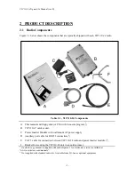
Figure 2.1 below shows the components that are typically shipped with each 

VIP 110-24

 radio.

Table 2.1 - VIP 110-24 Components

A

This manual and floppy disk (or CD) with Econsole program (

1

)

B

VIP 110-24

 outdoor unit.

C

Power Inserter Module with wall mount AC power supply

D

Auxiliary port cable for RS-232 connection (

2

)

E

CAT 5 cable for connection between VIP 110-24 radio and power inserter module (

2

)

F

Bracket for securing the VIP110-24 unit to an outdoor mast.

1

  One hard copy manual is supplied with each shipment.  An electronic version is available at

“www.ucwireless.com/manuals”.

2

  Not supplied with standard radio kit.  Available from Wi-Lan as optional equipment.

Summary of Contents for VIP 110-24

Page 1: ...VIP 110 24 Operator s Manual Rev F April 2003 Wi Lan Inc 2891 Sunridge Way N E Calgary Alberta Tel 403 273 9133 www wi lan com...

Page 2: ......

Page 3: ...can be determined by turning the equipment off and on the user is encouraged to try to correct the interference by one or more of the following measures Reorient or relocate the receiving antenna Incr...

Page 4: ...I LAN TECHNOLOGIES INC serial numbers warranty date or quality assurance decals have been removed or altered WI LAN TECHNOLOGIES INC also reserves the right to make product improvements without incurr...

Page 5: ...VIP 110 24 Operator s Manual rev E iv...

Page 6: ...18 4 2 3 Polarization 19 4 3 SITE SELECTION 19 4 3 1 Line of Sight Path 20 4 3 2 Radio Horizon Maximum Line of Sight Range 20 4 3 3 Point to Point Path Analysis 21 4 3 4 Antenna Orientation 27 4 3 5 C...

Page 7: ...WORK MANAGEMENT 67 7 1 TELNET 67 7 1 1 General 67 7 1 2 Starting a Telnet Session 67 7 1 3 Telnet Security 68 7 2 SNMP 68 7 2 1 Command Line Interface Versus SNMP 68 7 2 2 What is SNMP 69 7 2 3 Securi...

Page 8: ...through multiple hops Node by node Quality Of Service Options Minimum and maximum user data rate settings separate for inbound and outbound traffic Highly efficient air time utilization Efficient del...

Page 9: ...able The VIP 110 24 also includes a number of unique features that make the unit easy to install and operate Spectrum analysis capability with a graphical display of the energy in the RF band Accurate...

Page 10: ...110 24 outdoor unit C Power Inserter Module with wall mount AC power supply D Auxiliary port cable for RS 232 connection 2 E CAT 5 cable for connection between VIP 110 24 radio and power inserter mod...

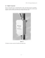
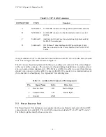
Page 11: ...mounted on a mast The radio is housed in a rectangular enclosure with two N female connectors at the top for connection to RF antennas and two special purpose connectors at the bottom for DC power Eth...

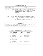
Page 12: ...ignment of the three pin auxiliary port connector The unit is shipped with a cover in this connector The connector can be used during installation as a console port and also as an audio antenna alignm...

Page 13: ...ber Indicates that the power inserter unit has DC power from the wall supply but no power is being drawn by the VIP 110 24 Green Indicates that the VIP 110 24 is drawing power WARNING The Power Insert...

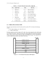
Page 14: ...24 carries the following signals 1 DC voltage to supply power to the VIP 110 24 2 10 Base T Ethernet data Both these signals are carried in a single CAT 5 cable The system is designed to allow cable...

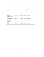
Page 15: ...strial shielded weatherproof cable for direct burial aerial and other severe environments 18 241 31 gray 18 241 11 beige Superior Essex Unshielded outdoor rated cable 5EXH04P24 BK R CMS PV CommScope U...

Page 16: ...port B could be an omni sector or directional antenna Leaf nodes do not have children so no antenna is connected to port B Each VIP 110 24 in a VINE network operates in a half duplex mode i e it may...

Page 17: ...d Add an R or an L to the end of the designator to indicate whether the radio is a repeater or a leaf 3 3 New Node Attachment and validation Besides polling the known child radios nodes configured as...

Page 18: ...reduces the potential for self created interference with other radios in the VINE network that are using the same channel If there is no interference from other sources a signal level at the receiver...

Page 19: ...each topology shows the commands required at each node to set the channel assignments 3 5 1 Point to point In a point to point network one radio is configured as the root with the antenna on port B a...

Page 20: ...ater on channel c1 If antenna B of the repeater is directional it may easily reject this unwanted transmission from the root Otherwise ensure that c1 and c3 are non overlapping 2 At the leaf while the...

Page 21: ...e repeaters the potential for self generated interference increases The way to reduce or avoid this self generated interference is to allocate one channel to all outbound transmissions from parents th...

Page 22: ...requency channels between 1R and its children and the secondary non overlapping set of channels between 1 2R and its children 3 Antenna polarization use horizontal antenna polarization between 1 2R an...

Page 23: ...e bridged 3 7 Quality of Service The VINE protocol is ideal for bursty traffic that is typical in data communications The available data throughput is allocated on demand to the nodes that are active...

Page 24: ...antenna cable length Therefore antenna installation is a vital part of system installation Improper installation may greatly reduce system performance possibly rendering the system inoperable This sec...

Page 25: ...oint applications where the direction of communication is known and fixed a highly focused directional antenna can be used to provide maximum sensitivity and power In addition because of its decreased...

Page 26: ...of the parabolic antenna determines polarization In setting up the VIP 110 24 system either vertical or horizontal polarization can be used as long as polarization is the same at both ends of each li...

Page 27: ...jects Because of the uncertainties of radio communication it is difficult to predict the results in conditions where obstructions exist The only valid advice is to try the proposed configuration and b...

Page 28: ...provide more reliable results 4 3 3 Point to Point Path Analysis A full point to point analysis should consist of at a minimum a background noise evaluation of all locations where radios are to be in...

Page 29: ...e any installation of any equipment is completed Although the graph of figure 4 1 provides a useful guide to antenna height requirements a more accurate determination of those requirements can be obta...

Page 30: ...Add the d value to the height of each obstruction plotted on the graph Another increment must be added to the height of each obstruction because of the Fresnel zone The required increment is 60 of the...

Page 31: ...ink margin at the sight Determine free space path loss using either table 4 1 the graph of figure 4 2 or the formula following figure 4 2 Table 4 1 Free Space Path Loss at 2 4 GHz Distance miles Path...

Page 32: ...18 20 22 24 26 28 30 32 34 36 38 40 42 44 46 48 50 Path Length miles 131 133 135 137 139 95 97 99 101 103 105 107 109 111 113 115 117 119 121 123 125 127 129 Path Loss dB 0 5 10 15 20 25 30 35 40 45...

Page 33: ...nerally connected directly to the radio connector However if an additional cable is used between the radio and the antenna cable the cable loss attenuation must be included in order to calculate the c...

Page 34: ...hoice of polarization horizontal vs vertical is in many cases arbitrary However interfering signals from such devices as cellular phones and pagers are generally polarized vertically and an excellent...

Page 35: ...den 9913 the loss is 4 3 6 Connector Loss Loss is introduced with each pair of cable connectors Attenuation losses of some standard cable types are shown in the following table Connector type Loss per...

Page 36: ...hreaded couplings mating antenna lead connectors should be clean and tight bayonet type connectors should not be used Weatherproof connectors must be used for outdoor connections to prevent corrosion...

Page 37: ...VIP 110 24 Operator s Manual rev E 30...

Page 38: ...f the repeater radio Use an Ethernet crossover cable if connecting the PC directly to the Power Inserter Unit or use a straight cable if connecting through a hub 2 Connect each Power Inserter Unit to...

Page 39: ...tion 6 describes the command language used to further modify the radio s operating parameters 5 2 Bench Check Out using radio auxiliary ports 1 Connect each VIP 110 24 Auxiliary Port to a terminal or...

Page 40: ...stallation NOTICE The antennas for the VIP 110 24 must be professionally installed on permanent structures for outdoor operations The installer is responsible for ensuring that the limits imposed by t...

Page 41: ...the installation instructions provided by the manufacturer of the lightning protection device used 5 3 2 Antenna Alignment When mounting the high gain antenna 24 dBi the proper antenna alignment is e...

Page 42: ...or this reason a narrow band transmitter will show up in the spectrum analysis report as a lobe with 18 MHz bandwidth Conversely you do not need to find a quiet 18 MHz wide region in the spectrum anal...

Page 43: ...s Institute ETSI regulations impose a limit of 20 dBm as the maximum Effective Isotropic Radiated Power EIRP for direct sequence spread spectrum systems operating in the 2 4 GHz band The installer mus...

Page 44: ...ands used to download and manage the various files stored in Flash PROM A more detailed explanation for each command can be found in section 6 File Utility command summary Command Description director...

Page 45: ...ne so install the utility program econ in the PC This utility program is distributed with the radios and can also be downloaded from the website Please refer to appendix E for instructions on how to i...

Page 46: ...ort time with the root running the new version and all other radios running the old version If the new firmware is incompatible with the old one the non root radios may not attach to the root In this...

Page 47: ...1 Verify that the new software is available in the local machine The download software for upgrade via Telnet must have a dwn extension e g vip01_05 dwn 2 Initiate a Telnet session with the radio as...

Page 48: ...xiliary Port 3 pin circular connector to a terminal or a PC running a terminal emulation program A special adapter cable is supplied by Wi LAN Configure the terminal settings as follows Baud rate 9600...

Page 49: ...he file is successfully installed issue the command directory to insure that the file has been loaded into memory 10 Issue the command set default program filename vipNN_NN where NN_NN file is new ver...

Page 50: ...is connected From this PC it is then possible to configure not only the radios directly connected to the LAN but also all other radios reachable through one or more RF hops Refer to Appendix E for ins...

Page 51: ...meter and value lists are context sensitive i e in order to solve ambiguities the command interpreter only considers parameters valid for current command or values valid for the current parameter The...

Page 52: ...o configuration can be password protected This password is set by the user with the change password command Once a password is set issue the lock command to prevent any unauthorized changes to the con...

Page 53: ...23 A From Children 25 B Max Cycle ms 100 NN Poll 1 5 18 B Max Bytes cycle 76000 NN Poll 2 35 18 B ETHERNET Single Node Reboot Timeout sec 900 Station t o sec 30 Antenna Alignment Aid Off Multicast t o...

Page 54: ...n configuration Examples load configuration source factory load lock This command locks the access to all the commands that can alter the radio configuration Once locked use the unlock command to rega...

Page 55: ...into the VINE RF network even during idle periods receive kbps 1 10000 Specifies the maximum data rate that the anchor radio will accept from its Ethernet addressed to this specific node even during i...

Page 56: ...subsidiary to the root or other repeaters A repeater node acts as a slave to its parent and as a master to its children Repeaters also keep searching for new child nodes by performing new node polls l...

Page 57: ...o children for the timeout specified by this command it will perform a reset This feature is useful if a command is issued to a remote radio changing its parameters in such a way that breaks the link...

Page 58: ...yet in the network respond to these poll packets in order to get attached This command configures the optional second channel and power used for transmissions of NNP packets the speed is always 2 Mbp...

Page 59: ...tdoors CAT5 cable operation at 100 Mbps may become unreliable For this reason the auto negotiate setting allows only 10 Mbps half or full duplex For operation at 100 Mbps you need to specify that spee...

Page 60: ...are shown in the format above if the date and or time commands have been issued or the unit has been able to catch a Network Time Protocol packet NTP since it was powered up Otherwise the Start Time s...

Page 61: ...e local but forward all other packets into the VINE RF network These are accounted separately in the report The times format indicates whether that entry is for a multicast MC address shows the time w...

Page 62: ...io only responds to requests from the specific IP addresses listed This list of authorized managers is also used for validating Telnet requests Refer to section 7 for an overview of Network Management...

Page 63: ...by the show command In order to align antenna A at a leaf or repeater node set the node parameter to 3 which is always the parent radio In a typical VINE application antenna B is a widebeam antenna th...

Page 64: ...ach source a separate line with the statistics of the NNP packets and other packets These statistics include a cumulative count of packets received and the Received Signal Strength RSS of those packet...

Page 65: ...ats defaults to graph During the test the RF input into the radio can be selected between one of the two antennas Note that even though the VIP 110 24 channels are spaced 2 MHz apart the receiver RF b...

Page 66: ...at the remote radio and missed packets on the reply link cumulative count as well as a percentage of the total and turn around time statistics minimum maximum and recent average To stop the test press...

Page 67: ...level settings allow the user to display only the events with the specified category range The reboot reasons region of the event log consist of the last four events that that caused the radio to rebo...

Page 68: ...ing it the default console speed bps baud rate bps 9600 or 19200 or 38400 or 57600 or 115200 Sets the Auxiliary port of the radio to the specified baud rate This setting is not saved in the radio conf...

Page 69: ...arameter If the destination parameter is omitted the file will be stored in Flash PROM with the same name as the source Note that the bin extension is not needed in the command The download method to...

Page 70: ...time The zone value is saved as part of the radio configuration If NTP packets are not available the user can initialize the radio date and time with either the date or time commands The parameters fo...

Page 71: ...y Displays the previous commands entered license key ASCII string The license command is used to turn ON or OFF a set of optional features or capabilities The key is a 35 character string combination...

Page 72: ...valent to power cycling the radio off and on time time hh mm ss date day month year zone zone code or offset This command is identical to the date command explained above except for the order of the p...

Page 73: ...VIP 110 24 Operator s Manual rev E 66...

Page 74: ...This initial configuration must be done using either the RS 232 console port or the ECON program Once the VIP has an IP address you must start the telnet application at the local machine and establis...

Page 75: ...ows one way to find its IP address is to open a DOS window and issue the command ipconfig 7 2 SNMP 7 2 1 Command Line Interface Versus SNMP Configuration settings on the VIP 110 24 are displayed and m...

Page 76: ...use SNMP the device must have an IP address 7 2 3 Security Considerations in SNMP SNMP was designed before the Internet grew commercial and the original design was not secure Later versions intended...

Page 77: ...110 24 Management Information Base MIB The VIP 110 24 implements only the core MIB II A management station will see 3 interfaces in the interfaces group 1 VINE bridge 2 Ethernet 3 Radio The first of t...

Page 78: ...ment 6 3 clear log region Event Logging 6 8 console speed bps baud rate bps File Utilities 6 9 copy file source destination File Utilities 6 9 date date time zone Miscellaneous 6 10 delete file filena...

Page 79: ...tion Parameters 6 4 min flow rate transmit kbps receive kbps Major Configuration Parameters 6 4 monitor environment channel input Installation and Link monitoring 6 7 monitor flow Installation and Lin...

Page 80: ...et default program filename File Utilities 6 9 save configuration destination Configuration Management 6 3 show tables table format Bridge Management 6 5 snmp authentication traps manager community ac...

Page 81: ...VIP 110 24 Operator s Manual rev E 74 Command Parameters Functional Group version Miscellaneous 6 10...

Page 82: ...f the radio configuration is omitted the value for that parameter is not modified For commands that are not part of the radio configuration if a parameter is omitted the value for that parameter defau...

Page 83: ...294 967 295 0 name ASCII string 11 max ucw serial no type root repeater leaf repeater anchor 0 1 0 location ASCII string 25 max contact ASCII string 25 max single node reboot timeout timeout sec 30 36...

Page 84: ...5 3600 600 show tables table radio nodes ethernet stations flow control format count times Internet Protocol IP Management Commands Command Parameters Values ip configuration address ip address netma...

Page 85: ...itor environment channel 0 50 input a antenna b antenna monitor flow monitor link node node name or node number clear no yes spectrum analysis input a antenna b antenna display graph table dwell time...

Page 86: ...0 200 min level 0 7 def 0 max level 0 7 def 7 max event save 0 7 5 print 0 7 3 File Utilities Command Parameters Values console speed bps baud rate bps 9600 19200 38400 57600 115200 copy file source f...

Page 87: ...Commands Command Parameters Values Factory Configuration date date dd mmm yyyy time hh mm ss zone offset or code GMT help command history license key 35 character string logout reboot time time hh mm...

Page 88: ...ta Rates one way 1 2 5 5 11 Mbps Receiver Sensitivity 10 6 BER 89 dBm 1 Mpbs 86 dBm 2 Mbps 84 dBm 5 5 Mbps 81 dBm 11 Mbps Data Interfaces Auxiliary Port RS 232 Ethernet Port 10 100 BaseT auto negotiat...

Page 89: ...VIP 110 24 Operator s Manual rev E 82...

Page 90: ...6 2 412 16 2 432 26 2 452 7 2 414 17 2 434 27 2 454 8 2 416 18 2 436 28 2 456 9 2 418 19 2 438 29 2 458 10 2 420 20 2 440 30 2 460 11 2 422 21 2 442 31 2 462 12 2 424 22 2 444 32 2 464 13 2 426 23 2 4...

Page 91: ...VIP 110 24 Operator s Manual rev E 84...

Page 92: ...d and definitely not more than the maximum number which currently is 4 System requirements Win95 Win98 Windows ME WinNT Win2000 WinXP NetBIOS installed WinPCap installed Note With regard to Windows NT...

Page 93: ...are interpreted as radio command unless a They start with the character which implies a comment b They start with the character which implies a local command Currently there is only one local command...

Page 94: ...0 78 24 22 BA 4F Inverse Screen Colors You can change the default settings white texture on black background by providing the b option which will change the settings to black characters on white backg...

Page 95: ...This introduces a side bar which enables the user to scroll up and down Available in Windows NT Only Troubleshooting Updates Common problems 1 Failed to open adapter This usually happens when you have...

Page 96: ...message or I get a session timeout application will be closed message An open session times out after 15 minutes of inactivity on the server side and 30 minutes on the client side Report a bug Update...

Page 97: ...VIP 110 24 Operator s Manual rev E 90...

Page 98: ...32 interface and the antenna alignment audio interface These cables can be manufactured by the user using the supplied wiring diagrams or may be purchased through Wi Lan Technologies Inc Auxiliary RS...

Page 99: ...5 Outdoor Solid Cond CommScope 5EXH04P24 BK R CMS PV 1 DESCRIPTION MANUFACTURER PART NO ITEM 1 8 RJ 45 Plug RADIO_ETH_TX 1 RADIO_ETH_TX 2 RADIO_ETH_RX 3 VDC 4 VDC 5 RADIO_ETH_RX 6 GND 7 GND 8 ITEM 2 I...

Page 100: ...VIP 110 24 Operator s Manual rev E 93 Instructions for assembly of the Switchcraft EN3CxF Connectors Three pin connector is shown Use same process for 8 pin...

Page 101: ...VIP 110 24 Operator s Manual rev E 94 Auxiliary Antenna Alignment Aid Cable Wi Lan Technologies Part Number C1064 008 Headphone Jack EN3C3F Connector Tip 1 1k 10 Ohm 2 3 Ring Shield...

Reviews: