VIP 110-24
Operator’s Manual (rev E)
- 31 -
5
INSTALLATION AND SETUP
The
VIP 110-24
units are shipped pre-configured to operate as “repeaters”. It is recommended that an
initial check be performed on the bench before a field installation.
For this bench check out you need two
VIP 110-24
units. One of the radios will be configured as the
“root” of the network and the other as a “repeater”. The first approach described below uses the
“Ethernet Console Program” to emulate the terminal across an Ethernet connection. The second
approach uses two terminals connected to the auxiliary port of the radios. Since the radio are to be
mounted close to the antenna and the use of the serial port will be inconvenient, UCW recommends
the use of the ethernet console program to communicate with and configure the radios.
5.1
Bench Check Out (using radio Ethernet connection)
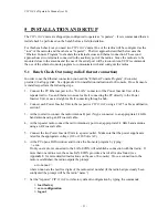
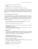
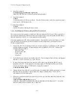
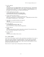
In order to use the Ethernet connection you need the “Ethernet Console Program” (Econsole)
provided in a floppy disk. See Appendix E for installation instructions for Econsole. Once Econsole
is installed, perform the following steps.
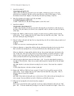
1.
Connect the PC Ethernet port to the “To LAN” connector of the Power Inserter Unit of the
repeater radio. Use an Ethernet crossover cable if connecting the PC directly to the Power
Inserter Unit, or use a straight cable if connecting through a hub.
2.
Connect each Power Inserter Unit to the respective
VIP 110-24
using a CAT 5 cable as defined in
section 2.
3.
At the root radio connect the radio Antenna B port (N type connector) to an appropriate 2.4 GHz
band antenna using an RF coaxial cable.
4.
At the repeater radio connect the radio Antenna A port to an appropriate 2.4 GHz band antenna
using an RF coaxial cable.
5.
Connect the two Power Inserter Units to a power outlet. Make sure that the power supplies are
rated for the appropriate voltage (110 or 220 Volts AC).
6.
At the PC open a DOS window and invoke the Econsole program by typing:
> econ
If only one radio is connected to the LAN, ECON will establish a connection with that radio. If
more than one radio are in the same LAN ECON provides a list of all radios found (see
Appendix E for more detailed instructions on the use of Econsole). Once a connection to the
radio is established, the radio outputs the prompt:
ucw-nnnnn #>
where nnnnn are the last five digits of the radio serial number (if the radio had previously been
configured the prompt will be the radio “name”).
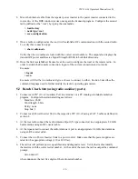
7.
Set the “repeater”
VIP 110-24
to its factory default configuration by typing the commands:
> load factory
> save-configuration
> logout
Summary of Contents for VIP 110-24
Page 2: ......
Page 5: ...VIP 110 24 Operator s Manual rev E iv...
Page 37: ...VIP 110 24 Operator s Manual rev E 30...
Page 73: ...VIP 110 24 Operator s Manual rev E 66...
Page 89: ...VIP 110 24 Operator s Manual rev E 82...
Page 91: ...VIP 110 24 Operator s Manual rev E 84...


