28% Cap 232 Assembly Manual
Steps 9, 10, 11.
Installation of fuel system, radio and con-
trol linkages
These 3 subjects are combined on one page because this is the part where you get to do
things your way. We have only done a few things to get you started.
1. There is plenty of room to cut holes in one or both fuse sides that will fit the popular in-
tegrated switch/charge jack assemblies. These are
available from Maxx Products, Cermark, JR, and
probably several other vendors. Some trimming
may be required. Since the fuse sides are balsa new
holes are easily cut with a razor knife.
If you do
cut into the fuse side for any reason do not cut
the 1/4” balsa stringers at the top and bottom of
each side.
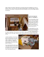
2. The fuel tank can be mounted on the tray beneath
the wing tube. Putting it there minimizes changes
in balance as the engine burns off fuel.
3. There is a tray which is meant to hold the receiver, battery pack(s), and one or two rud-
der servos if a pull-pull is chosen.
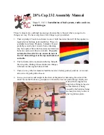
4. In case you need to add weight in the front of the plane for balancing, the sides of the
motor box at the front are a good place to mount the receiver packs. Range check your
radio with the engine run-
ning before flying to be sure
no interference is being
caused by the batteries being
in close proximity to the en-
gine’s ignition system.

