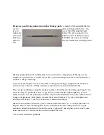
about 1/16” in front of it. The cowl mounts are already set, use the cowl face to
align the engine. Right thrust is already built into the firewall.
3. Glue the hinges with whatever you like to use. I like pro-bond polyurethane or
gorilla glue because it foams and fills the voids, but it makes a mess when it
foams so clean it off. After hinging you should seal the control surface gaps.
4. Hatch mounts are obvious, drill 1/8” hole and use a 4-40 blind nut inside.
Mount the canopy using the method you prefer; screws, tape, glue. Whatever
works for you.
5. The horizontal stab assembly mounts on one 1/2” aluminum tube. One 4mm
screw is used at each side to retain the stab assemblies. Use lock washers on
them. Put pins through the rear antirotation dowels to act as a backup to the
side screws.
6. The control surfaces have pre-drilled hard points to accept rocket city type
horns. The rudder has two hardpoints, the upper one is for the rudder tiller and
the lower one is used to steer the tailwheel. A 6-32 tiller is sufficient in that po-
sition. Two springs are supplied for this purpose.
7. Servo installation should be obvious. Elevator servos trays are located in the
tail below the horizontal stab. Rudder servo trays are below and behind the ele-
vator servos. Don’t cut out the wrong one, and don’t cut out the rudder servo
trays until you are sure you will be using tail-mounted servos. Slots for pull-
pull cables are located below the rudder servo trays. Throttle servo installation
is up to you, pictures of two installations are in the main manual.
8. Landing gear and tank should be pretty obvious by now, the LG should be use
as a template to drill through the ply plate and the aluminum brackets.
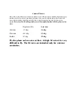
9. Balance the plane and set the control throws according to the details in steps
13 and 14.

