376
326
~
+
•
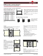
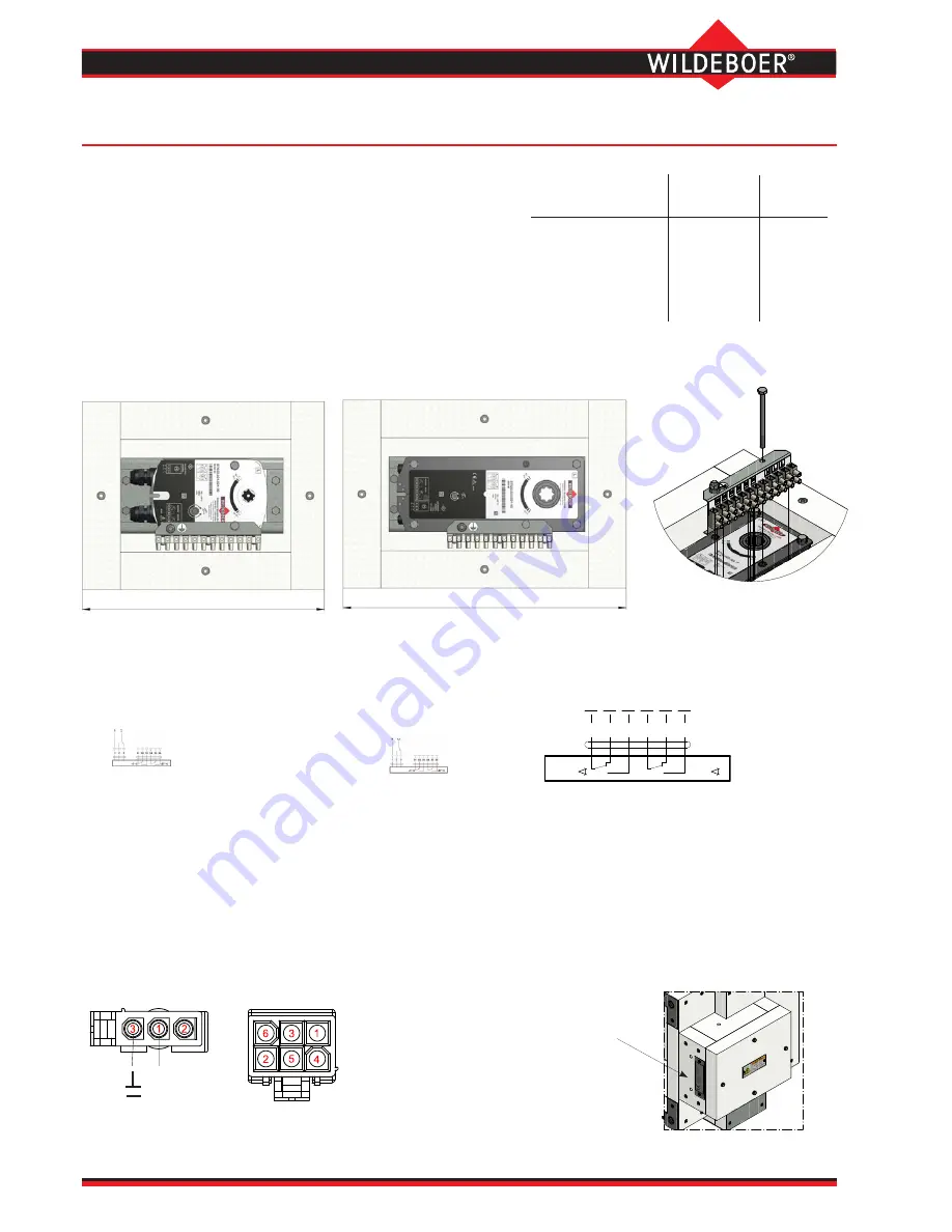
The limit switch for the "CLOSED position" (S1 contact with S2) of the smoke control damper is actuated at angle position < 3°.
•
The limit switch for the "OPEN position" (S4 contact with S6) of the smoke control damper is actuated at angle position ≥ 87°.
•
The intermediate position is signalled in angle position > 3° and < 87° (S1 contact with S3 and S4 contact with S5).
User Manual 5.32 (2018-05) 30
Subject to change
Series EK92
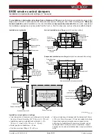
The
electric drive
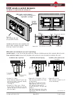
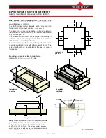
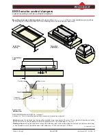
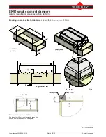
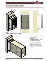
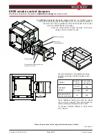
is located to the side of the smoke control
damper, inside the calcium silicate
casing
.
The motor drive can be accessed by unscrewing the casing cover.
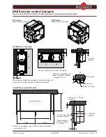
Electrical cables should be guided through the walls of the casing
for the motor drive on site.
Holes should be arranged for these as shown and matched to the
diameter of the cables.
Depending on the height H of the smoke control damper, motor
drives with difference performance data can be fitted:
EK90 smoke control dampers
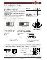
Electrical connection (1) motor drives
Electrical connection
Motor drives M1
24 V AC/DC
Electrical connection
Motor drives M2
230 V AC
Motor drive for standard design with
heights H = 200 to 450 mm
Motor drive for standard design with heights
H > 450 up to 800 mm and for special design of
electrical connection
Protection class IP54, runtime:
≤
60s
Motor drive
M1
M2
24 V AC/DC
230 V AC
Standard design
Height H
≤
450 mm
7.5 W / 9 VA 5 W / 12 VA
Height H > 450
mm
12 W / 18 VA 8 W / 15 VA
Special design of
12 W / 18 VA 8 W / 15 VA
electrical connection
Option:
terminal strip
for
electrical connection.
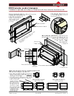
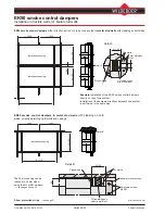
Motor drives for EK90 smoke control dampers
,
shown with the optional terminal strip for easy electrical connection.
Additional casing for control units
⇒
see page 32
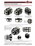
Configuration of AMP connectors on
motor drives 24 V AC/DC
S1 ... S6
S1 S2
S3 S4 S5 S6
<3°
<87°
Schematic circuit diagram:
Limit switch for "CLOSED position" actuated
in < 3° angle position, smoke control damper
is in "CLOSED position".
Limit switch assignment S1 to S6
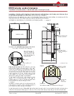
Hole diameter = cable diameter
Casing for the motor drive
Recommended
hole positions
for
inserting the electrical
cables
are
labelled at the factory.
Required holes should be produced
as required on site.
1 = Ground neutral
2 = Rotation direction "OPEN"
3 = Rotation direction "CLOSED"

