background image

User Manual 5.32 (2018-05) 33

Subject to change

Series EK92

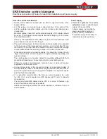
Installation

• 

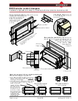
EK90 smoke control dampers, series EK92, must 

be installed and operated in accordance with 

this user manual and in compliance with all other  

regulations.

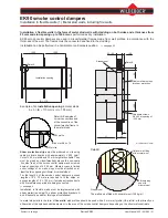
  In addition, smoke control dampers must be installed 

tension-free and appropriately aligned.

  Air flows in the smoke extraction ducts must not 

adversely  affect  the  torques  acting  on  the  damper 

blade by the motor.

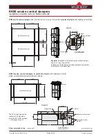
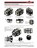
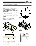
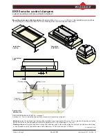
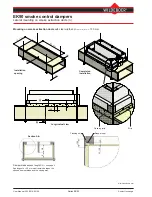
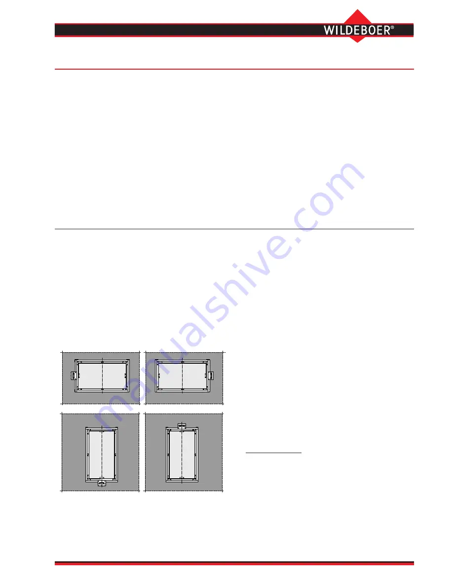
  Installation can be performed in a horizontal or vertical 

axis position.


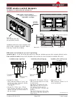
Casings  should  be  installed  in  installation  openings 

in  walls  such  that  they  lie  largely  flush  on  the  bot

-

tom  side.  If  remaining  gaps  are  filled  with  mineral 

wool,  a  melting  point  of  ≥  1000°C  must  be  verified 

for this. Shear protection brackets should be installed 


accordingly.


Structural requirements and concerns, as well as rele

-

vant manufacturer's specifications, should be verified 

and observed by the customer.

• 

Smoke  control  dampers  for  outside  air  supply  must 

be installed such that heavy moisture penetration is 

avoided, in particular in the event of frost exposure. 

• 

Assembly,  electrical  wiring,  connections  etc.  must  be 

produced on site.

  Smoke extraction ducts and electrical equipment must 

be suitable, and must be correctly installed and con-

nected.

• 

Inspection  openings  must  be  provided  on  site  in  the 

smoke extraction ducts if necessary. 

Functional testing/servicing

  In accordance with German regulations, smoke extrac

-

tion systems must be serviced and kept ready for oper-

ation by the owner. The smoke control dampers must 

be tested for correct functioning at six-month intervals. 

If successive tests are passed without any defects, the 

next text may be carried out after one year.

• 

Operating instructions

 for the EK90 smoke control 

dampers, Series EK92, are available on the Internet at 

www.wildeboer.de.

  In general, actuating (closing and opening) the smoke 

control  dampers  is  sufficient  in  testing  the  function. 

This can be performed by means of remote actuation.

  EK90 smoke control dampers do not generally require 

any maintenance work.

  The  cleaning  of  smoke  extraction  systems  should  be 

performed in an operation-dependent manner, and 

also includes the smoke control dampers.

  Repairs  or  service  work  are  required  in  the  event  of 

malfunctions. 

  Original spare parts must be used.

• 

EK90  smoke  control  dampers,  Series  EK92,  are  suit

-

able for smoke extraction systems and for combined 

systems for smoke extraction and building ventilation.

  They supersede the former EK90 smoke control damp-

ers in accordance with approval Z-78.2-7 and EK90 

smoke control dampers with ventilation function in 

accordance with approval Z-78.3-104. 

• 

EK90 smoke control dampers, series EK92, in 

sys-

tems only for smoke extraction

 are usually closed. 

  In the event of fire, all of them or only those required 

can be opened from the outset. As the fire develops 

and smoke is released, other ones can be opened and 

the previously opened ones can be closed again.

• 

EK90  smoke  control  dampers,  Series  EK92,  required 

for  building  ventilation  in 

combined systems for 

smoke extraction and building ventilation 

are usual-

ly opened, whereas others are closed. 

  In the event of fire, the smoke control dampers required 

for smoke extraction are opened or are kept open, 

while others are closed or remain closed. 

 As the fire develops and smoke is released, other 

EK90 smoke control dampers, series EK92, can be 

opened and previously opened ones can also be 

closed.The function with HOT classification is verified.

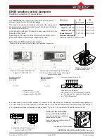
 EK90 smoke control dampers, series EK92, can still be 

opened 25 minutes after the onset of full fire exposure.

The function with MA classification is verified.

Function of smoke extraction systems with EK90 smoke control damper, Series EK92

EK90 smoke control dampers

Function in smoke extraction systems - installation - functional testing/servicing

Summary of Contents for EK90

Page 1: ...n of this document shall prevail Maintenance free EK90 smoke control dampers meet all requirements in accordance with European standards and are universal for all applications Further uses and extende...

Page 2: ...l damper Opened smoke control damper Ventilator for smoke extraction and also for ventilation Smoke extraction duct with fire resistance period Smoke extraction duct without fire resistance period Smo...

Page 3: ...g and damper blades made from abrasion proof safe corrosion resistant calcium silicate that is suitable for higher temperatures The edge protection profiles are made from gal vanized steel and include...

Page 4: ...action ducts for heights H Length L Length L1 Length L2 up to 450 mm 350 mm 330 mm 20 mm larger than 450 mm 400 mm 380 mm 20 mm Standard widths B mm 200 225 250 275 300 325 350 375 400 450 500 550 600...

Page 5: ...698 0 689 0 682 0 676 250 0 768 0 732 0 704 0 682 0 664 0 649 0 637 0 626 0 617 0 602 0 590 0 581 0 573 0 566 0 561 275 0 669 0 636 0 610 0 590 0 574 0 560 0 549 0 539 0 531 0 517 0 506 0 497 0 490 0...

Page 6: ...t B 500 mm with H 500 mm lies in the field A Max 20 m s There is no restriction here see also table on page 7 v A Max m s 6 5 5 5 3 2 1 20 30 70 100 7 200 250 300 350 400 500 600 700 800 1000 1200 150...

Page 7: ...0 2000 4000 8000 vA 5 m s 16 8 2 4 8 12 15 19 vA 10 m s 10 4 1 4 6 9 12 16 vA 15 m s 5 2 0 4 6 7 11 15 vA 20 m s 2 1 2 5 6 7 11 14 Examples 1 2 3 Width B x height H Inflow velocity vA 10 15 20 m s Vol...

Page 8: ...4 34 34 33 33 33 33 33 33 33 33 33 33 33 33 400 m h 1440 1620 1800 1980 2160 2340 2520 2700 2880 3240 3600 3960 4320 4680 5040 Pa 6 6 6 5 5 5 5 5 5 5 5 4 4 4 4 dB A 34 33 33 33 33 33 33 33 33 33 32 32...

Page 9: ...32 32 32 400 m h 5400 5760 6120 6480 6840 7200 7560 7920 8280 8640 9000 9360 10080 10800 Pa 4 4 4 4 4 4 4 4 4 4 4 4 4 4 dB A 32 32 32 32 32 32 32 32 32 32 32 32 32 32 450 m h 6075 6480 6885 7290 7695...

Page 10: ...50 50 400 m h 2880 3240 3600 3960 4320 4680 5040 5400 5760 6480 7200 7920 8640 9360 10080 Pa 26 24 23 22 21 21 20 20 19 19 18 18 17 17 17 dB A 51 51 51 51 51 51 51 50 50 50 50 50 50 50 50 450 m h 3240...

Page 11: ...50 50 50 50 50 50 50 50 50 50 400 m h 10800 11520 12240 12960 13680 14400 15120 15840 16560 17280 18000 18720 20160 21600 Pa 17 16 16 16 16 16 16 16 16 16 16 16 15 15 dB A 50 50 50 50 50 50 50 50 50...

Page 12: ...44 43 42 42 41 dB A 63 62 62 62 62 62 62 62 62 61 61 61 61 61 61 400 m h 4320 4860 5400 5940 6480 7020 7560 8100 8640 9720 10800 11880 12960 14040 15120 Pa 58 54 51 49 48 46 45 44 43 42 41 40 39 38 3...

Page 13: ...2 62 62 350 m h 14175 15120 16065 17010 17955 18900 19845 20790 21735 22680 23625 24570 26460 28350 Pa 45 44 44 44 43 43 43 43 43 42 42 42 42 42 dB A 61 61 61 61 61 61 61 61 61 61 61 61 61 61 375 m h...

Page 14: ...17640 Pa 118 112 107 103 99 97 94 93 91 88 86 84 83 82 81 dB A 71 71 70 70 70 70 70 70 70 70 70 70 69 69 69 375 m h 5400 6075 6750 7425 8100 8775 9450 10125 10800 12150 13500 14850 16200 17550 18900...

Page 15: ...520 21600 22680 23760 24840 25920 27000 28080 30240 32400 Pa 100 99 98 97 97 96 96 95 95 95 94 94 94 93 dB A 70 70 70 70 70 70 70 70 70 70 70 70 70 70 325 m h 17550 18720 19890 21060 22230 23400 24570...

Page 16: ...0 788 0 825 0 861 0 898 0 934 1 007 1 080 H B 200 225 250 275 300 325 350 375 400 450 500 550 600 650 700 200 0 023 0 027 0 030 0 033 0 036 0 040 0 043 0 046 0 049 0 056 0 062 0 069 0 075 0 082 0 088...

Page 17: ...3 76 78 80 83 85 88 90 93 98 102 225 67 70 72 75 77 80 82 85 87 90 92 95 100 105 250 69 72 74 77 79 82 84 87 89 92 94 97 102 107 275 71 73 76 78 81 84 86 89 91 94 96 99 104 109 300 72 75 78 80 83 85 8...

Page 18: ...installation s 25 mm Gap for mineral wool filling s 10 to 25 mm Calcium silicate support bearings with the dimensions 100 mm x 100 mm x 25 mm for gaps s 25 mm are included in delivery Support bearings...

Page 19: ...ection brackets B are fitted onto the oper ation side front of the smoke control damper and are attached using M8 threaded rods and nuts that pass through the wall or ceiling Dowel attachment see page...

Page 20: ...ng DA 125 mm up to 180 mm Shear protection brackets A can be used laterally and shear protection brackets B above and below Spacing DA 22 mm Shear protection brackets A or B can be used laterally Spac...

Page 21: ...vertical sides For the length L of the smoke control dampers excess lengths of Z 70 mm are required to fit the strips or excess lengths of Z 100 mm if smoke extraction ducts with fire resistance peri...

Page 22: ...in the same way EK90 smoke control dampers in metal stud walls with cladding on both sides directly adjoining rigid walls and ceilings Detail A Shear protection strips see page 21 Detail B The 52 mm s...

Page 23: ...smoke control dampers see page 28 Example Left hand side smoke extraction duct made from sheet steel right hand side smoke extraction duct made from wall boards with fire resistance period The connec...

Page 24: ...specifications The screw sizes specified in the following drawings relate to smoke extraction ducts with a thickness of 35 mm The screw lengths should be adapted in the case of greater thicknesses Ins...

Page 25: ...installation Extensions must be produced from duct specific materials in the cross section 50 mm x 70 mm glued to the smoke extraction duct and screwed on using chipboard screws with a diameter of 5 x...

Page 26: ...smoke extraction ducts with clear widths Hsmoke control damper 130 mm Installation opening Completed installation Section A A Longitudinal view Detail from section A A Damper blade excess length 2 se...

Page 27: ...om of movement of the damper blade should be taken into account when mounting the protective grilles see damper blade excess length on page 4 Extensions in the form of smoke extraction ducts made from...

Page 28: ...sion of an EK90 smoke control damper together with connected smoke extraction ducts Weights of EK90 smoke control dampers see page 17 Example EK90 smoke control dampers between vertical smoke extracti...

Page 29: ...1 H Installation opening 22 Z Mineral wool 100 kg m or Mortar Calcium silicate strips for shear protection Chipboard screws 4 x 60 at spacing of 200 mm Installation direction NL NR 22 W Installation...

Page 30: ...AC DC Electrical connection Motor drives M2 230 V AC Motor drive for standard design with heights H 200 to 450 mm Motor drive for standard design with heights H 450 up to 800 mm and for special design...

Page 31: ...ng the connection cables this should be factored in with large cross sections shorter lengths or a higher electrical operating volt age accordingly The same applies to connection cables for operating...

Page 32: ...through the walls of the extra casings can be produced on site The clear dimension of the additional casing depends on the type of EK90 smoke control damper Design Heights H mm Clear dimen sion mm Sta...

Page 33: ...eboer de In general actuating closing and opening the smoke control dampers is sufficient in testing the function This can be performed by means of remote actuation EK90 smoke control dampers do not g...

Page 34: ...should be ordered see page 4 Option Versions with reduced frame height for Motor drive on the left NL Motor drive on the right NR see page 29 Motor drive 24 V AC DC with AMP connectorM1 230 V AC M2 se...

Page 35: ...With special seals to open and close the smoke con trol dampers during fire exposure For installation in rigid walls and ceilings with mortar or mineral wool in flexible walls and onto or between smo...

Page 36: ...wildeboer eu WEENER EMS Ulm office Telephone 49 0 7392 9692 0 Fax 49 0 4951 950 27299 E mail info ulm wildeboer de ULM Leipzig office Telephone 49 0 34444 310 0 Fax 49 0 4951 950 27298 E mail info le...

Reviews: