Heating
CLOSED
OPEN
terminal box
Control voltages
to
Potential equation
(on site)
Control voltages
230 V AC or 24 V AC/DC
Cable
Cable
Fire damper
CLOSED OPEN
Control voltages
230 V AC or 24 V AC/DC
Cable
Cable
CLOSED
OPEN
CLOSED OPEN
Fire damper
white
white
white
green
green
brown
brown
white
white
white
green
green
brown
brown
User Manual 5.02 (2016-10)
13
Subject to change
Series FK120
FK90 fire dampers
Electrical connections, installation, functional testing, servicing
Actuators EM-1, EM-2 and RM-1
Actuators M220-7, M24-7
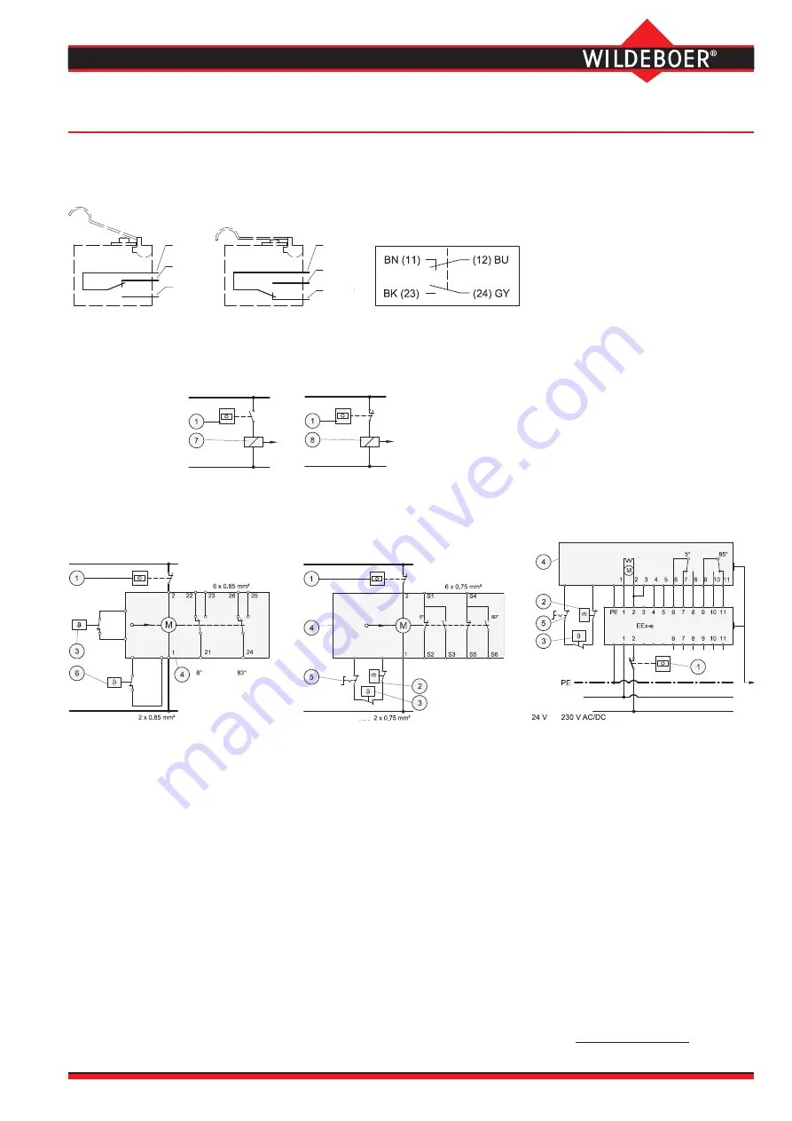
Limit switches
on thermal-mechanical release mechanisms
The CLOSED limit switches are actuated when the fire damper is closed, and the OPEN
limit switches are actuated when the fire damper is open.
Limit switch not actuated
Limit switch actuated
Actuators M220-9/V, M24-9/V
Remote release
E-Ex limit switch
Installation
•
FK90 fire dampers, series FK120, must be installed based
on the instructions in this user manual. The technical
regulations and national statutory regulations must be obser
-
ved during installation.
In Germany, this means the “Technical Building Regulations”
(VV TB) and the "Guideline on Fire Protection Requirements
Pertaining to Ventilation Systems" (Lüftungsanlagenrichtlinie -
LüAR).
FK90 fire dampers meet these requirements and generally
recognised technical regulations.
•
Electric wiring
must be installed by the customer.
•
Potential equalisation conductors
to bridge flexible
connection pieces on fire dampers can be fastened
with metal screws if they are made of copper up to a
cross-section of 6 mm² or made of aluminium.
•
Fire dampers in
potentially explosive atmospheres
must
be grounded in accordance with regulations.
Functional testing and servicing
•
Fire dampers must be serviced by the owner and tested
periodically to ensure they are functioning correctly.
The intervals largely depend on the system operation. Rele
-
vant regulations should be followed.
•
FK90 fire dampers, series FK120, are maintenance-free due
to fully enclosed components, corrosion-resistant materials
and precise manufacture.There is no need for regular clea
-
ning and lubrication, which would otherwise be necessary.
•
Functional tests on FK90 fire dampers, series FK120, are
generally limited to a release and re-opening.This can be
performed remotely with electric actuators.
•
Repairs or service work are required in the event of malfunc
-
tions.Original spare parts must be used for this.
•
Cleaning work required in ventilation systems for hygiene
reasons must be performed in an operation-dependent
manner, and also includes the fire dampers.
Operating instructions
for the FK90 fire dampers, series FK120, can be downloaded online at www.wildeboer.de/en
.
W220, G24
Closed during current flow
WU220, GU24
Closed during power interruption
Control voltages 230 V AC or 24 V DC
Limit switch not actuated
Connection cable colour coding
1 Thermostats, smoke detectors and switches
should only be installed if required.
On site delivery.
2 Thermal-electrical release element
70°C or 95°C; EM-1,
EM-2 and RM-1 only 70°C!
3 Thermal cut-off approx. 70°C
4 Electric actuator with limit switches for
OPEN-CLOSED position indicator.
The illustration shows the de-energised
operating position where the fire dam
-
pers are closed.
•
The plugs on the connection cables can
be removed if they are not being used.
•
Due to their in-built thermal release ele
-
ments, all actuators must be stored at tem
-
peratures not exceeding 50°C.
5 Switches or buttons for testing the actuators
6 Thermal-electrical release element 70°C or
100°C with plug-in connection for testing the
actuator.
7 Lifting solenoid
8 Magnetic clamp
The right to allow for variations in delivery from
the versions shown remains reserved
.


