background image

User Manual 5.0-2 (2016-10)

 14

Subject to change

Series FK120

FK120 

- - - - - -

Size

B [mm] x H [mm] x L [mm]

⇒ 

see page 3

Option:

 Damper blade

 Metal frame made of 1.4301 


stainless steel

• 

Galvanized metal cover

• 

Metal frame and metal cover made of 

1.4301 stainless steel


Metal frames/metal covers made of stainless steel should be 

used with casings coated with epoxy resin.

⇒ 

see page 3

Option:

 Casing design

 Casing with inner and outer epoxy 


resin coating.

⇒ 

see page 3

Option: 

Additional casing openings

 132-mm 


with cover; position of the  

  opening: top/bottom/top + bottom

Option: 

Release temperature

 95°C or 100°C 

1)

• 

70°C corrosion protected 

2)

⇒ 

see pages 2 to 5

Option:

 Limit switches


 E-CLOSED

• 

E-OPEN

  These limit switches can also be combined with the follow- 

  ing remote releases!

Option:

 Remote release


 GU24

• 

WU220

• 

G24

• 

W220

• 

P

• 

P2

Option:

   Explosion-protected

Option:

   Explosion-protected limit switch

 EX-CLOSED

• 

EX-OPEN

Option:

 Electric actuators

• 

M220-9/V

 M24-9/V

• 

M220-7

 M24-7

Option:

  Electric explosion-protected 

actuators

 EM-1 

 RM-1

• 

EM-2

⇒ 

see pages 5 and 6

FK90 fire dampers 

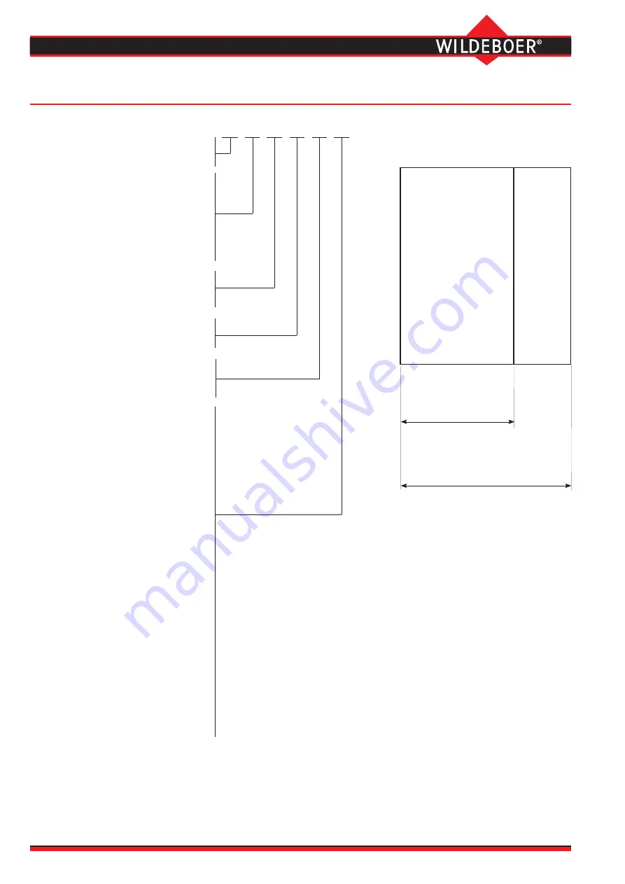
Ordering FK90 fire dampers, series FK120

1) 

only for actuators EM-1, EM-2, RM-1.

2) 

only for mechanical release mechanisms.

}


Standard

200
225
250
275

300
325
350
375

400
450

500

550

600
650

700
750

800
850

900
950

1000

1050

1100
1150

1200
1250

1300
1400

1500

Heights H up to 

1000 mm can be 


combined with widths B 

up to 1000 mm

Lengths L = 400 mm and 500 mm

All dimensions B and H can thus be combined!

}


Standard

}


Lifting solenoids

}


Magnetic clamps

}


Pneumatic cylinders

Heights H up to 800 mm can be 

combined with widths B up to 

1500 mm

also E-CLOSED together with E-OPEN

Only for thermal-mechanical release mechanisms

Actuators with thermal-electrical release 

mechanisms and limit switches

}


also EX-CLOSED together with EX-OPEN

Standard widths B and heights H

Intermediate dimensions are available in 

5-mm increments.

Summary of Contents for FK90

Page 1: ...series FK120 Heights up to 1000 mm Fire resistance period up to 120 minutes Fire classification EI 30 60 90 120 ve ho i o S C10ooo Hygiene certificate Environmental Product Declaration according to IS...

Page 2: ...arge free cross section Maximum volume flows Minimum pressure drop Extremely low sound power level Connection holes for profiles from 20 mm in height Two control openings inspection openings for viewi...

Page 3: ...tability free dom of damper blade movement minimum pressure drop and low noise level Option Casing with epoxy resin powder coating Replaceable damper blade made of high temperature re sistant corrosio...

Page 4: ...ld smoke extraction are country specific Electric spring return actuators also close the fire dampers if the supply voltage is interrupted They reopen the fire dampers as soon as the voltage is presen...

Page 5: ...n ded and vertical positions on site Terminal box FK90 fire dampers Release mechanisms and actuators 2 Thermal mechanical release mechanism with 70 C release element Option with coated 70 C release el...

Page 6: ...ocations must not be changed on site H J3 K K400 K500 200 170 225 160 250 145 275 135 4 300 120 17 325 110 29 350 95 42 375 85 54 400 70 67 450 45 92 500 20 117 17 550 142 42 600 7 167 67 650 32 192 9...

Page 7: ...637 0 684 0 780 0 876 1050 0 117 0 142 0 167 0 192 0 217 0 268 0 318 0 368 0 418 0 469 0 519 0 569 0 620 0 670 0 720 1100 0 122 0 149 0 175 0 202 0 228 0 281 0 334 0 386 0 439 0 492 0 545 0 598 0 650...

Page 8: ...m m 0 0 5 1 B 1 2 0 0 M e t a l d a m p e r b l a d e B 1 5 0 0 m m 1 4 0 0 v 12 m s A Volume flow m h v 12 m s A Operating pressure User Manual 5 0 2 2016 10 8 Subject to change Series FK120 FK90 fir...

Page 9: ...400 800 500 600 Width B mm 200 250 300 350 400 500 600 700 800 Height H mm Volume flow V m h 225 275 200 300 400 600 800 1000 2000 3000 4000 6000 8000 10000 20000 30000 40000 50000 150 900 1000 900 10...

Page 10: ...Afree 0 098 m Dps 29 Pa vA 7 4 m s LWA 47 dB A Sound power level LW Oct for the octave mid frequencies f Hz 63 125 250 500 1000 2000 4000 8000 LWA dB A 47 47 47 47 47 47 47 47 DL7 4 m s dB 5 6 1 3 6...

Page 11: ...always located to the H side on the casing of the fire dampers see page 6 FK90 fire dampers Installation in rigid walls and ceilings and in metal stud walls 1 with cladding on both sides The fire damp...

Page 12: ...rete in solid construction Rigid walls and ceilings must have bulk density 450 kg m Metal stud walls should be clad on both sides in two or more layers with 12 5 mm GKF plasterboard Installation openi...

Page 13: ...nd tested periodically to ensure they are functioning correctly The intervals largely depend on the system operation Rele vant regulations should be followed FK90 fire dampers series FK120 are mainten...

Page 14: ...Option Explosion protected limit switch EX CLOSED EX OPEN Option Electric actuators M220 9 V M24 9 V M220 7 M24 7 Option Electric explosion protected actuators EM 1 RM 1 EM 2 see pages 5 and 6 FK90 f...

Page 15: ...metal stud walls Enclosed maintenance free thermal release mechanism 70C 95 C or 100 C for manual single handed operation corrosion resistant release element with two electrical limit switch es for s...

Page 16: ...nventional control systems in buildings is complex Special plug and play functionality allows control systems for fire dampers to be designed built and connected in parent hierarchy without any measur...

Reviews: