User Manual 5.12 (2019-09) 8
Subject to change
Series FR92K
FR90 fire dampers
in short lengths
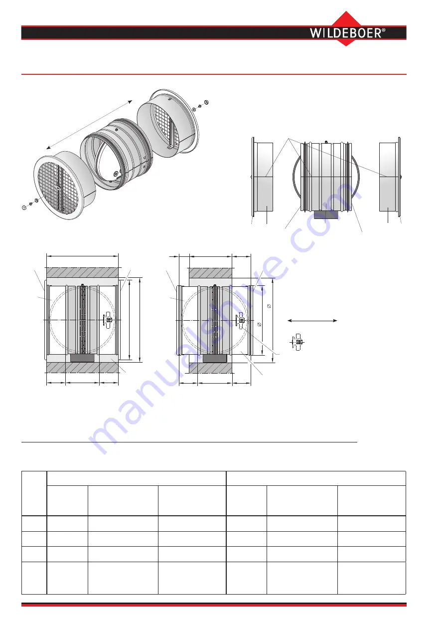
Installation in air transfer applications with protective grille on both sides;
without non-return valve
Minimum wall thicknesses for protective grille SG1 installation flush with the wall
DN
Without non-return valve
⇒
see page 8
With non-return valve
⇒
see page 9
Wall
thickness
W [mm]
Connecting piece AS
Length L1
Connecting piece AS
Length L2
Wall
thickness
W [mm]
Connecting piece AS
Length L1
Connecting piece AR
Length L2
100
≥
210
55
55
≥
210
55
55
125
≥
210
55
55
≥
210
55
55
160
≥
210
55
55
≥
210
55
55
200
≥
220
75
Shorten on-site to
60 mm
75
Shorten on-site to
60 mm
≥
235
75
Shorten on-site to
60 mm
75
100
L2
L1
Installation opening
DN + 50
W
D1
SG1
SG1
AS
AS
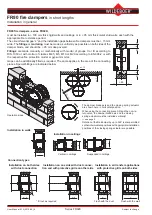
The damper blade can be installed with the axis
in the vertical or horizontal position, or anywhere
in between; the same applies to the protective
grille and connecting pieces.
Installation with excess lengths
Ü
1
and / or Ü
2
Installation flush with the wall
100
L2
L1
W ≥
95 (100)
05
+
N
D
Installation opening
N
D
SG2
SG2
Ü1
Ü2
AS
AS
Operation side
Connection length
on the
•
Operation side L1
•
Non-operation side L2
Excess length
on the
•
Operation side Ü
1
•
Non-operation side Ü
2
If Ü
1
= L1, Ü
2
= L2 + 100 mm - wall thickness W
When the fire damper is open,
the flow direction can be from
both sides.
Longitudinal pipe seam
1
G
S
K
2
9
R
F
SG1 AS
Non-operation side L2
Operation side L1
AS
Complete installation
Flow
directions
All dimensions in mm


