WILDEN PUMP & ENGINEERING, LLC
28
WIL-12310-E-04
W I L - G A R D ™ D I A P H R A G M S E N S O R
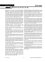
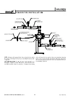
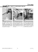
Step 1
The Wil-Gard™ sensor wires must
be installed between the primary
diaphragm and the back-up
diaphragm, on both sides of the
pump, at the 6 o’clock position. They
should be positioned approximately
half the distance to the shaft from
the edge of the diaphragm.
Step 2
Prior to installing the liquid chamber,
and after positioning the Wil-Gard™
sensor cable between the primary
and back-up diaphragms, run the
sensor cable along the diaphragm
bead but outside the pump. Now
install the liquid chamber and large
clamp band.
Step 3
When installing the liquid chamber
and large clamp band, route the Wil-
Gard™ sensor cable to the inside of
the large clamp band fastener. Next,
reconnect the Wil-Gard™ module.
NOTE: Use caution to ensure that
the sensor wires are not damaged
or pinched by the clamp band.
Wil-Gard™ Diaphragm Sensor Installation
Summary of Contents for PX4 series
Page 9: ...PX8 P X 8 S A N I F L O H S P E R F O R M A N C E S A N I F L O...
Page 22: ...N O T E S...
Page 41: ......
Page 42: ...N O T E S WILDEN PUMP ENGINEERING LLC 40 WIL 12310 E 04...

