Wilger
Installation and Operation Manual
Wilger Electronic Flow Monitoring System
Page | 13
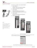
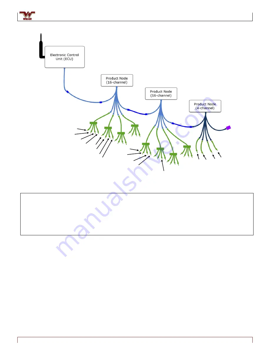
Figure 21. System Structure
ECU to Product
Node Extension
Cable (if req’d)
(For informaton on
Y-adapter cables
see Appendix)
Quad Sensor
Cables
16-Channel
Harness
Node-to-node
Extension Cable
(if req’d)
Node Harness
Terminator
4-Channel
Harness
Node 1
Node 2
Node 3
16-Channel
Harness
Node-to-node
Extension Cable
(if req’d)
A
B
C
D
1A1
1A2
1A3
1A4
1B1
1B2
1B3
1B4
2A1
2A2
2A3
2A4
3A1 3A2 3A3
3A4
Single Sensor
Cables
ADVANCED:
Using an ECU to Node Y-adapter
If more convenient, an ECU to Product Node Y-adapter cable can be used to split the system into two sections allowing the ECU
to be located in the middle of the implement with a series of Product Nodes on each side.
For more information on the use of the ECU to Product Node Y-adapter cable, see Appendix 1.
D
C
B
A
*2B3


