Wilger
Installation and Operation Manual
Wilger Electronic Flow Monitoring System
Page | 23
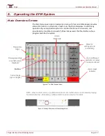
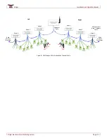
Figure 4-12
Configuring the Flow Measurement Sensors
The Sensor Setup screen has four pages. On these pages you can group and list flow
sensors so that they display together, the way you want to see them while
operating the machine. You can also add page labels to indicate the location or
product type. Identify the sensors by their numbers, as connected to their
respective product harnesses. When a product type is selected (1-3), the associated
outlet spacing, alarm threshold, and jet selection/calibration number are displayed
for verification on the Main Overview screen.
NOTE: Before configuring these pages, decide how you want to see the information. For
example, do you want information for two different products to appear on the same page?
Sensor information is split into two parts on each page. (e.g. 1A and 1B).
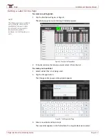
Opening the Sensor Setup Screen
1.
On the Main Overview screen, tap the Sensor Settings icon.
The Sensor Setup page #1 appears.
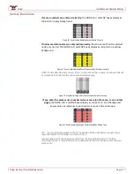
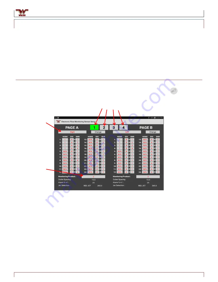
Figure 34. EFM Sensor Setup Page
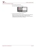
Any of four sensor pages can be displayed by tapping the number associated
with the desired page. Each sensor page is divided into two parts: A (on the
left) and B (on the right). Each page can display up to 48 sensors (24 on A; 24 on
B). A and B can display sensors associated with the same or different products.
2.
Tap the number of the desired page. That page appears.
Sensor Page Numbers
Page Label
Product
Number


