Wilger
Installation and Operation Manual
Wilger Electronic Flow Monitoring System
Page | 27
Sensor Box Colors
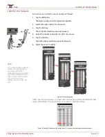
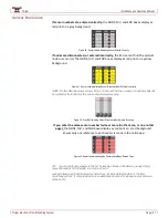
If sensor numbers are entered correctly,
the NODE, DIV, and SNR boxes display as
red print on a gray background.
Figure 40. Sensor Labels Indicating Sensor Entered Correctly
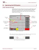
If nodes are disconnected, or entered incorrectly,
the ECU cannot find the product
node or sensor(s). The NODE, DIV, and SNR boxes display as red print on a yellow
background.
Figure 41. Sensor Labels Indicating Sensor Disconnected or Entered Incorrectly
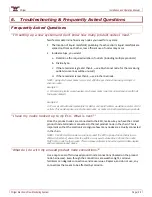
NOTE: On the Main Overview screen, if the ECU cannot find the a sensor, its indicator ball will
be located at the bottom of the screen and displayed as gray.
Figure 42. Gray Ball Indicating Sensor Disconnected or Entered Incorrectly
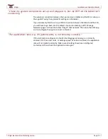
If you enter the same sensor number twice or more (on the same, or on another
page),
the NODE, DIV, and SNR boxes display as red print on a red background.
Ensure only one reference to each sensor is made in the entire app.
Figure 43. Sensor Labels Indicating the Sensors Have Been Entered Twice
TIP: You can segregate sensors in the list by leaving a blank slot between groups. Simply
leave the node as N/A (default) in a slot on screen.
Leaving blank slots (balls) between sensors does not impede the function of the flow
monitoring system; it only provides more customization options for leaving spaces between
sections, etc.


