Wilger
Installation and Operation Manual
Wilger Electronic Flow Monitoring System
Page | 8
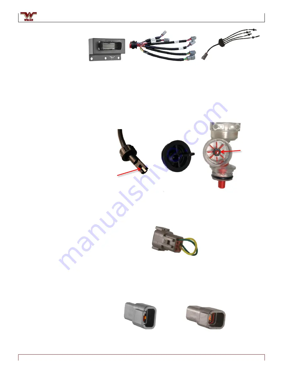
Figure 9. 16CH Node, 16CH Node Harness and Quad Sensor Cable
16-channel (16CH) node, 16CH node harness and quad-sensor cable
– Enables the
16CH node harness to connect to four quad-sensor cables (allowing up to 16
sensors per 16CH product node) to be connected and communicate with the
system. Each 16CH node has six connectors: four 6-pin female Deutsch connectors
(for quad-sensor cables), one 8-pin female Deutsch connector (for connecting to the
next node in the chain, or to a terminator), and one 8-pin male Deutsch connector
(for connecting to the previous node in the chain, or the ECU).
Figure 10. Hall Effect Sensor and Encoder Wheel
Sensor and Encoder
– Hall effect sensor detects rotation of the encoder magnet on
the wheel, producing pulses at a rate representative of flow.
Figure 11. ECU Harness Terminator
8-pin node harness terminator
– Terminates the series (chain) of product node
harnesses that originate at the ECU. The terminator will always be plugged into the
last product node(s) of the chain. (Advanced: If an ECU to Node Y-adapter is used at
the ECU, two terminators are required – one on each end of the chain.)
Figure 12. 4CH Node Sensor Connector Cap and 16CH Node Sensor Connector Cap
4CH and 16CH node sensor connector caps
– Protect unused sensor connectors
from corrosion
Encoder
Magnet
Hall
Effect
Sensor
Flowmeter
Cap


