Wilger
Installation and Operation Manual
Wilger Electronic Flow Monitoring System
Page | 15
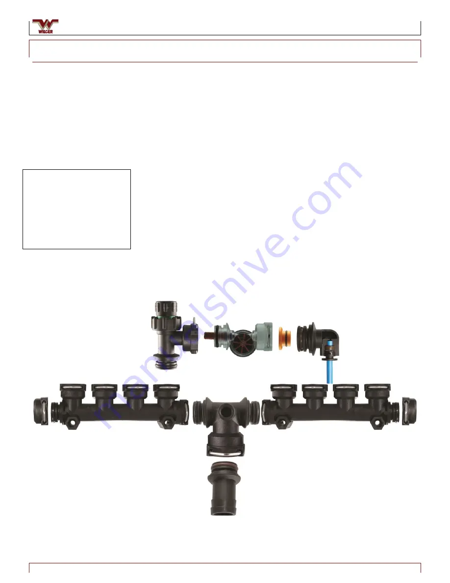
Figure 22. Example Plumbing
Installing the Plumbing
Plumbing Manifolds
1.
Use an ORS Tee (#20526-00) to connect the manifolds together and an end cap
(#20521-00) at each end.
2.
Install the preferred inlet size into the ORS Tee.
3.
Determine the EFM jet required for the flow range required by your application.
4.
Add the jets into each EFM body. (They only fit into the in-flow side of the EFM
body.)
5.
Connect an electronic flow meter (EFM) sensor to each check valve outlet.
6.
Connect a manual ON/OFF check valve to the top of each EFM sensor. (This
allows the run to be shut off for maintenance.)
7.
Add the ORS metering orifices to the outlet fittings, sized as required by your
application equipment outlets.
Example:
Six sections of eight runs each, for a total of 48 runs.
Center-feed each section using two 4-outlet manifolds (#20574-00), with a
manual ON/OFF check valve (#20551-00) mounted on top, an EFM body
(#20580-00) mounted to the check valve, and an outlet (with an option for a
metering orifice) attached to the EFM body.
Jet Ranges:
Green jet: 0.04 to 0.12 US GPM
Red jet: 0.10 to 0.31 US GPM
Blue jet: 0.18 to 0.98 US GPM
Black jet: 0.57 to 1.53 US GPM


