Wilger
Installation and Operation Manual
Wilger Electronic Flow Monitoring System
Page | 31
7.
Appendix
Appendix A: Using an ECU to Product Node Y-Adapter Cable
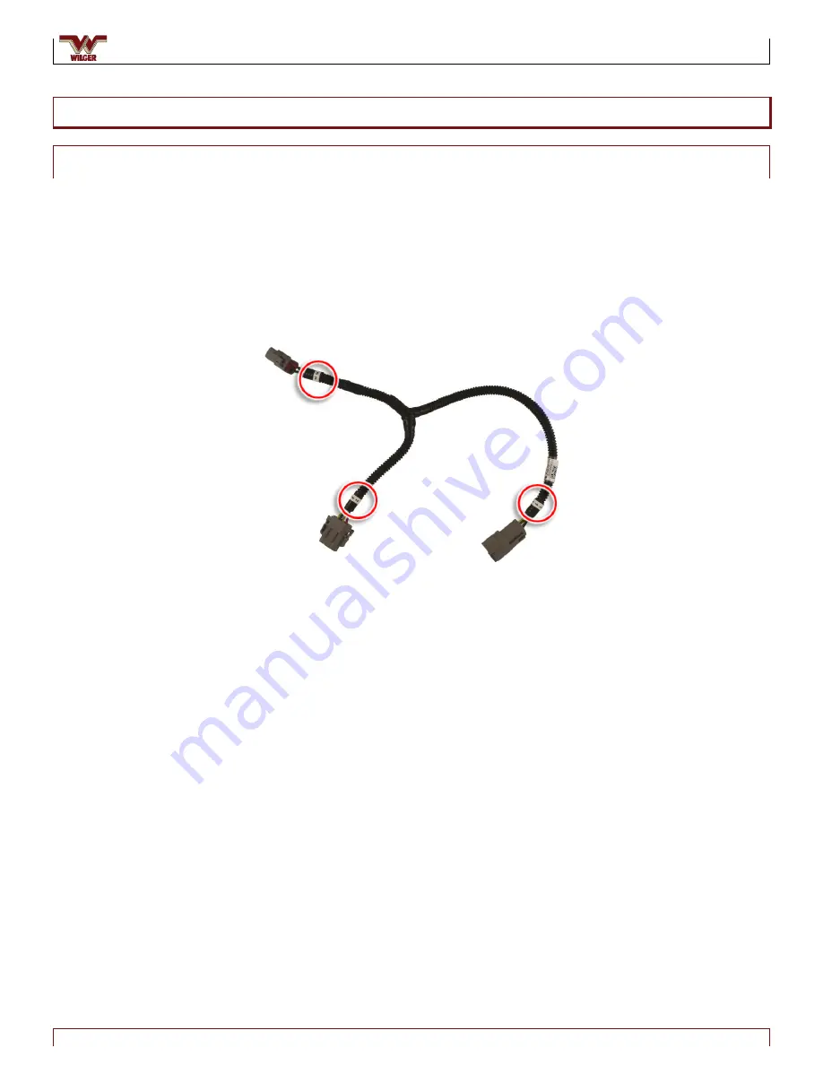
An ECU to Product Node Y-adapter cable allows you to locate the ECU in the middle
of your implement, and run wiring to product nodes on both sides. One advantage
is to ensure the best reception of the Wi-Fi signal by the tablet computer.
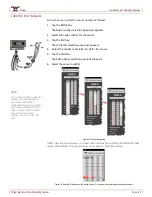
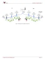
The Y-adapter cable has three connectors labelled 1, 2 and 3. Connector 1 plugs into
the connector from the ECU. Connector 2 is typically connected to nodes on the
right-hand side of the implement; Connector 3 is typically connected to nodes on
the left-hand side of the implement.
Figure 46. Y-Adapter Cable Connections
When using a Y-adapter cable, numbering of the product nodes and sensors starts
at 1 with the first node on the right-hand side (#2 connector on the Y-adapter) and
increments until the right-hand terminator is reached. Numbering continues from
the first node connected to the left-hand side (#3 connector on the Y-adapter) and
proceeds to the left-hand terminator.
“Right”
First series of nodes. Count starts at 1 and
proceeds to the last node connected to this leg.
“Left”
Second series of nodes starts counting after
the last node in the “Right” series
Connects to the ECU
1
2
3

