background image

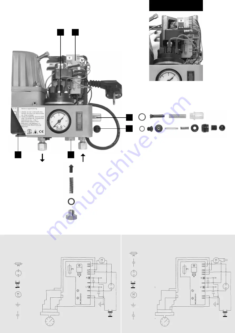
Type 240.902

Wiring diagram, type 180.902

Wiring diagram, type 240.902

B

C

D

E

F

A

Fuse

Control lamp

Push button

Motor

Earth

Condenser

(suppressor 

element)

Fuse

Condenser

Control lamp

Push button

Motor

Earth

Condenser

(suppressor 

element)

Summary of Contents for OILPRESS 180.902

Page 1: ...al air pressure of 1 bar is applied to the pressure storage vessel through the valve located in the upper part of the storage vessel The air can there fore escape over the course of time by Single line removal no return flow For all interlinked battery tank systems without non return valves in the suction line and for individual tanks without non return valves in the suction line for further detai...

Page 2: ...ring diagram type 180 902 Wiring diagram type 240 902 B C D E F A Fuse Control lamp Push button Motor Earth Condenser suppressor element Fuse Condenser Control lamp Push button Motor Earth Condenser suppressor element ...

Page 3: ...X 020 232 Hood X X 099 422 Screw set for hood X X 100 422 Cover with screws X X 002 412 Pumpe X X 030 422 Spare parts for pump X 002 422 Pump complete X 017 232 Gear wheel X X 012 252 Lug screw X X 003 232 Manometer X X 110 422 Push button with connecting wires X 003 412 Motor complete X 063 202 Fan X 198 422 Motor complete X 445 422 Intermediate flange complete X 113 202 Terminal rail X 072 312 C...

Page 4: ...t off valve can be ordered under article no 594 912 Supply line OILPRESS pressure storage units allow the use of a single line supply system see Piping diagram The line can be laid in any way required Oil pressure regulators must be installed so that the permissible pressure range of the oil regulator of 125 mm 3000 mm of oil is not exceeded at the combustion point The line from the oil pressure r...

Reviews: