background image

Page 4   WILKERSON 

OPERATIONS

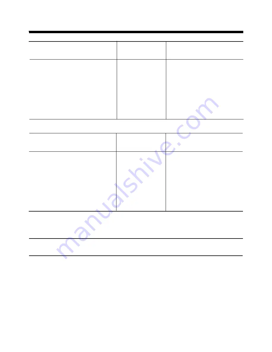
Water-Cooled Performance Specifications (60 Hz)

Performance Specifications: Flow Capacity (dm

3

/s) (50Hz)

Air-Cooled Performance Specifications (60 Hz)

Flows* at 37.7° C

Comp

Full

Model

Inlet Air Temperature 

Rating

Load

Shipping

Number

2-4°C Dew Point**

Voltage

(HP)   

Amps 

Weight

(dm

3

/s/hr)

WRA-0250-4

99

380/50/3

2.0

4.4

660

WRA-0300-4

118

380/50/3

2.5 5.2

675

WRA-0400-4

158

380/50/3

3.2 6.4

690

WRA-0500-4

197

380/50/3

3.8

7.7

700

All inlet and outlet air connections are: 2" NPT.
Specifications apply to air-cooled, water-cooled and 50 hertz.

Air flow rates are based on 100 psig (7 bar) inlet pressure and 100°F inlet air temperature.

System

COMPRESSOR DATA

Full

Model

SCFM

Load

Fan

Number

Flow

Voltage

HP 

Full Load Amps

LRA

Amps

CFM

Shipping

WRA-0250-2

250

230/60/1

2.0 9.9

53

12.1

1700

660

WRA-0250-3

250

230/60/3

2.0

6.6

49

8.8

1700

660

WRA-0250-4

250

460/60/3

2.0

3.3

24

4.4

1700

660

WRA-0300-2

300

230/60/1

2.5 12.7

64

14.9

1700

675

WRA-0300-3

300

230/60/3

2.5 7.7

49

9.9

1700

675

WRA-0300-4

300

460/60/3

2.5 3.9

24

5.0

1700

675

WRA-0400-2

400

230/60/1

3.2 17.2

95

19.4

1870

690

WRA-0400-3

400

440/60/3

3.2

10.8

65

13.0

1870

690

WRA-0400-4

400

460/60/3

3.2 5.3

27

6.4

1870

690

WRA-0500-2

500

230/60/1

3.8 21.5

46

23.7

1870

700

WRA-0500-3

500

230/60/3

3.8

13.3

92

15.5

1870

700

WRA-0500-4

500

460/60/3

3.8

6.6

116

7.7

1870

700

System

COMPRESSOR DATA

Full

Model

SCFM

Load

Number

Flow

Voltage

HP 

Full Load Amps

LRA

Amps

Shipping

WRA-0250-2

250

230/60/1

2.0 9.9

53

9.9

660

WRA-0250-3

250

230/60/3

2.0

6.6

49

6.6

660

WRA-0250-4

250

460/60/3

2.0

3.3

24

3.3

660

WRA-0300-2

300

230/60/1

2.5 12.7

64

12.7

675

WRA-0300-3

300

230/60/3

2.5 7.7

49

7.7

675

WRA-0300-4

300

460/60/3

2.5 3.9

24

3.9

675

WRA-0400-2

400

230/60/1

3.2 17.2

95

17.2

690

WRA-0400-3

400

440/60/3

3.2

10.8

65

10.8

690

WRA-0400-4

400

460/60/3

3.2 5.3

27

5.3

690

WRA-0500-2

500

230/60/1

3.8 21.5

46

21.5

700

WRA-0500-3

500

230/60/3

3.8

13.3

92

13.3

700

WRA-0500-4

500

460/60/3

3.8

6.6

116

6.6

700

Summary of Contents for WRA-0250-2

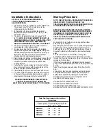
Page 1: ...N NEVER OPERATE THIS DRYER ABOVE THE RATED OPERATING CONDITIONS OPERATION ABOVE SPECIFIED CONDITIONS WILL RESULT IN DECREASED PERFORMANCE POSSIBLE DAMAGE TO THE UNIT AND OR PERSONAL INJURY OWNER OPERA...

Page 2: ...ation Instructions and Start up Procedure Page 5 Preventive Maintenance Dryer Dimensions and Recommended Wilkerson Air Accessories Page 6 Compressed Air Circuit Page 7 Refrigeration Circuit Page 8 Con...

Page 3: ...t which comes in contact with dry treated compressed air will stay cleaner will not corrode and will last longer Rejection rates of your end products will drastically reduce when using dry treated air...

Page 4: ...quires dirt and oil free air then appropriate particulate or coalescing filtration is required Electric Drains 9 Proper drainage of accumulated liquids is essential to proper system operation Should l...

Page 5: ...4 1700 660 WRA 0300 2 300 230 60 1 2 5 12 7 64 14 9 1700 675 WRA 0300 3 300 230 60 3 2 5 7 7 49 9 9 1700 675 WRA 0300 4 300 460 60 3 2 5 3 9 24 5 0 1700 675 WRA 0400 2 400 230 60 1 3 2 17 2 95 19 4 1...

Page 6: ...R Start up Procedure NOTE THE DRYER HAS A REFRIGERANT CRANKCASE HEATER PRIOR TO INITIAL START UP THE CRANKCASE HEATER SHOULD BE ENERGIZED FOR 24 HOURS BEFORE TURNING ON THE DRYER POWER TO THE CRANKCAS...

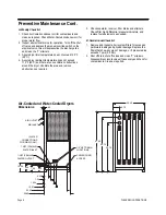
Page 7: ...remove obstructions as required 5 Check separator receiver filter drains and strainers Check filter high differential pressure indicators and replace fouled elements as needed B Semi Annual Checklist...

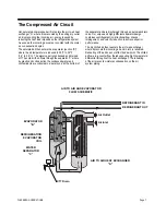
Page 8: ...ntaminants are collected in a quiet zone at the bottom of the separator and are discharged through an automatic drain valve Our unique and highly efficient separator design combines centrifugal action...

Page 9: ...liquid refrigerant removes the heat from the compressed air by evaporation The hot gas bypass valve G controls the temperature of the evaporator by sensing low evaporator pressure and injecting hot d...

Page 10: ...eat exchanger surfaces in the aftercooler water or air cooled are the principal cause of high inlet air temperatures to dryer Check air compressor as well Lack of lubrication excessive wear compressor...

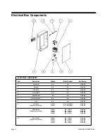
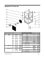
Page 11: ...ALL 87 685 000 7 Cover ALL ALL 63 685 000 8 Start Relay 230 60 1 WR 0250 0300 2 87 040 000 Single Phase Units Only 230 60 1 WR 0400 0500 2 87 041 000 9 Start Capacitor 230 60 1 WR 0250 2 87 056 000 Si...

Page 12: ...00 3 Hot Gas By Pass Valve ALL WR 0250 52 021 000 ALL WR 0300 52 021 000 ALL WR 0400 52 024 000 ALL WR 0500 52 024 000 REFRIGERATION COMPONENTS Item Description Voltage Model Number Part Number 4 Filt...

Page 13: ...embly ALL 14 138 000 2 Panel Back ALL 63 673 000 3 Panel Exhaust ALL 63 674 000 ALL WATER COOLED 63 091 000 4 Panel Inlet ALL AIR COOLED 63 672 000 5 Panel Front Left ALL 63 774 000 6 Panel Front Lowe...

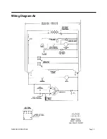
Page 14: ...WILKERSON OPERATIONS Page 13 Wiring Diagram Air...

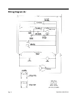
Page 15: ...Page 14 WILKERSON OPERATIONS Wiring Diagram Air...

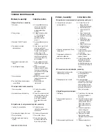
Page 16: ...Residual liquid water in piping D Drain all drop legs and system points and allow time for dry air to purge system Problem Caused By Corrective Action III Liquid water in compressed air system caused...

Page 17: ...ct way to file a warranty claim The following Warranty Procedure clearly outlines the obligations of Wilkerson Corporation and the procedure to be followed when processing a warranty claim WILKERSON R...

Page 18: ...PRESSURES Inlet air temperature ___________________ F C Outlet air temperature _____________________ F C Inlet air pressure___________________psig bar Outlet air pressure _____________________psig bar...

Reviews: