background image

1

2

2

3

3

4

4

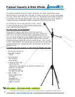
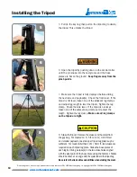
1. 

To Ensure Safe Installation: 


Select a level site to deploy the 

system that has no more than a 5

°

 slope.  Beware of surroundings and 

ensure that the center of the site is approximately 2.1m / 7 sq. ft.  The 
center of the site is where the tripod will be located in the installation.  
Ensure that the site has adequate overhead and ground clearances.  
The overhead clearance must be at least the height of the mast.  The 
ground clearance must be a radius equal to the height of the mast.  
For example, for a 4m / 13.1 ft. mast, ensure that the site has an 
overhead clearance of 4m / 13.1 ft. and a clear radius of 4m / 13.1 
ft. from the center of the site.

2. 

Unzip the wheeled bag, remove the tripod, guy bag and 

accessory bag.

3. 

With all three base plates of the tripod on the ground, 

loosen each leg clamp by turning the knob to the left.  

4. 

 Step on the base plates and lift the tripod up until the 

legs are fully extended.  Lock each clamp by turning the 
knob to the right until tight.  

Installing the Tripod

Do not duplicate, alter, or copy without the written consent of The Will-Burt Company. © Copyright 2013 The Will-Burt Company

9

www.antennamast.com

Summary of Contents for AntennaMast AM2 with EZ RAZE

Page 1: ...Model AM2 with EZ RAZE Payload Elevation System Operator s Manual www antennamast com ...

Page 2: ... and accessories The AntennaMast is available in 5 cm 2 in diameter and maximum height of 15 meters The AntennaMast will be referenced as the mast in the remainder of this manual By adding accessories the mast can be configured with 2 3 or 4 arms in 6 12 24 36 or 44 inch 15 30 60 cm or 1 meter lengths Optional payload adapters offered are Bolster plate Cup holder NATO plate Blank plate Page 6 expl...

Page 3: ...s 7 Installating the Tripod 9 10 Deploying the Mast 11 Deploying the EZ RAZE System 12 16 Installing the Accessories 17 Guying the Mast 18 19 Disassembling Maintaining the Mast 20 Customer Support Warranty Information 21 Do not duplicate alter or copy without the written consent of The Will Burt Company Copyright 2013 The Will Burt Company 3 www antennamast com Table of Contents ...

Page 4: ...understand the installation instructions before installing the drain kit Do not deploy the mast if power lines are less than 80 ft 24 4 m from the center of the deployment site Do not attempt to deploy the mast on soft or loose soil The base plate and guy stakes could become unstable under wind loading and cause the mast to fall Do not attempt to deploy or retrieve this mast during electrical stor...

Page 5: ...us injury Keep clear of moving parts while operating mast Relocation Hazard Relocating the mast during operation or after extension could result in death or serious injury Do not relocate the mast during operation or while extended Lifting Hazard The mast is intended to lift a specific payload for lighting surveillance or communication use only Any other use without written consent is prohibited a...

Page 6: ...d the current wind speeds at deployment two or three people are required to raise a 2m 8 ft to 15m 49 2 ft mast One person is typically required to load the mast tubes while one or two people manage the guy lines Typically single staking the tripod base plates is sufficient Contingent upon the payload weight and the current wind speeds at deployment three to five people are required to raise a 13m...

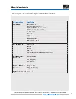
Page 7: ...ator s Manual Quick Reference Sheet Guy Accessory Kit Ground Stakes Guy lines Hammer Stake Puller Manual Lifter supplied in place of Mast Tube Lift Winch EZ RAZE Payload Elevation Kit EZ RAZE Carriage EZ RAZE Top Tube EZ RAZE Winch Mast Tube Lift Winch Kit Orange Lift Plate Some models Orange Winch w Key Payload Accessory Kit As ordered Do not duplicate alter or copy without the written consent of...

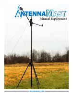
Page 8: ...Manual Deployment www antennamast com ...

Page 9: ...he height of the mast For example for a 4m 13 1 ft mast ensure that the site has an overhead clearance of 4m 13 1 ft and a clear radius of 4m 13 1 ft from the center of the site 2 Unzip the wheeled bag remove the tripod guy bag and accessory bag 3 With all three base plates of the tripod on the ground loosen each leg clamp by turning the knob to the left 4 Step on the base plates and lift the trip...

Page 10: ...of the adjacent leg clamps and adjust the length Tighten the leg clamp Make sure all leg clamps on the tripod are tight 8 Stake theTripod Remove the stakes and hammer from the guy bag For masts 2m 6 5 ft to 12m 39 3 ft tall and smaller payloads one stake per tripod leg plate may be sufficient For masts taller than 12m 39 3 ft two stakes are required on each tripod leg plate Stake the base plates o...

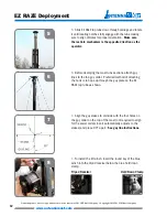
Page 11: ...cating notches on the bottom of the mast tube Orient this dimple toward you during deployment of the mast 3 Lift the tube until there is one hand width from the bottom of the tube and tighten the clamp 4 To install the EZ RAZE system open up the restrain system by engaging the kick stand lever to the lower bar Then slide the EZ RAZE carriage over the top of the tube section until resting on the to...

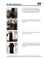
Page 12: ... through the guy plate on the EZ RAZE top tube as shown 7 Align the guy stakes to coincide with the four holes on the guy collar on the top of the mast not required to align for the swivel collar since it automatically adjusts to the stakes and place 90 apart See guy line instructions 1 To install the lift winch insert the round key of the blue winch into the tripod receiver below the blue hold do...

Page 13: ...outing is always between the spool and standoffs Never route the cable over standoffs to the next contact point 4 Take the end of the cable and feed it up through the 2 eyelets on the EZ RAZE carriage 5 Then feed the cable through the top pulley of the tip and back down the other side of the carriage Make sure the cable passes back down through the backside 180 to single eyelet Do not duplicate al...

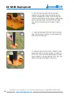
Page 14: ...he cable from the top seating the ball into the recess in the bottom of the black receiver plate 8 Then take the end of the cable and feed it through the bottom hole in the black receiver plate from the side with the slot cutout between the two holes EZ RAZE Deployment 16 9 Correct installation of cable end to the receiver plate www antennamast com Do not duplicate alter or copy without the writte...

Page 15: ...e in the tripod Match dimple profiles if payload alignment is required EZ RAZE Deployment 19 18 20 13 While holding onto the tube that was just loaded loosen the lower clamp to the left Push the tube up until only a hand s length is visible then tighten the clamp to the right The manual lifter can also be used to push the tubes up Repeat this step until all tubes are loaded Tighten tripod clamp to...

Page 16: ...ke the base plate of the base tube by driving the stake with the hammer provided at a point aligned with pivot point of the base plate 16 Stake the base plate of the tube by driving the stake through holes with the hammer provided For masts 2m 8 ft to 12m 40 ft tall and smaller payloads one stake may be sufficient For masts taller than 12m 40 ft two stakes are required depending on the soil type 2...

Page 17: ...d angle for the arm line up the arm hole with the arm collar hole and pin the arm in place by pressing the button 1 3 Match a corresponding angle for the payload adaptor line up the arm hole with adapter hole and pin the arm in place by pressing the pin button Do not duplicate alter or copy without the written consent of The Will Burt Company Copyright 2013 The Will Burt Company 17 www antennamast...

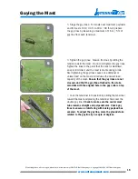
Page 18: ...to the eyelet of the stake and that the eyelet is pointing towards the tripod If possible drive the stakes a distance equal to the mast height from the center of the mast Consult The Will Burt Company for modified distance 3 Clip the carabineer to the swiveling guy collar which is done before raising the mast 4 Clip the carabineer of each of the tensioners to the ring of the guy stake www antennam...

Page 19: ...nd reduces the overall load capacity of the mast Ensure that the guy lines are not crossed and that the guy line attached to the stake coincides with the aligned hole in the guy collar on top of the mast 7 Lock the tensioner into position by sliding the tensioner toward the mast and placing the tensioner hook over the double guy line Check to make sure the center mast tube remains straight and per...

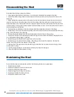
Page 20: ... ground stakes from the tripod base plate and place them in the guy bag 7 Loosen the clamps on the tripod legs and allow the legs to retract within themselves bringing the mast to a comfortable working height Optional 8 Detach the guy line hooks from the guy collar on the top tube 9 Detach the guy line hooks from the stakes Wind the guy line around the tensioner Remove the stakes Place the guy lin...

Page 21: ... in writing to Will Burt within thirty 30 days of the discovery of defect Failure to provide notice as required hereby shall be conclusive evidence that the product was in conformity with the warranty and Will Burt shall be released from any and all liability relating to the product Will Burt may either send a service representative or have the product returned to its factory at Buyer s expense fo...

Reviews: