4
SoundPlus
™
Infrared Listening System
MAN 133D
CHA
AUDIO IN
CHB
AUDIO IN
SOUND SYSTEM
MOD 232 MODULATOR (REAR)
BASEBAND SIGNAL
CHA
AUDIO IN
CHB
AUDIO IN
SOUND SYSTEM
MOD 232 MODULATOR (REAR)
TO ADDITIONAL EMITTERS
(IF NECESSARY)
WIR TX9 EMITTER (REAR)
RX22-4 RECEIVERS
(WIRELESS)
A265
Power On
Baseband On
Multi-Channel Infrared Transmitter
Made in U.S.A.
24 VAC
NC
CAUTION
RISK OF ELECTRIC SHOCK
DO NOT OPEN
WARNING: TO REDUCE THE RISK OF FIRE OR
ELECTRIC SHOCK DO NOT EXPOSE THIS
EQUIPMENT TO RAIN OR MOISTURE.
Power In:
24VAC
50-60Hz
35VA
Power Supply Wiring:
Baseband Signal Wiring:
Baseband Signal Wiring:
Note: It is normal for this unit to feel warm while it is in operation.
Plug
Use NEC, Class 2 Wiring, 18 ga. minimum,
200 ft. (70m) maximum length (18 ga.)
Use 50 Ohm Coaxial Cable (RG58)
Use RG58 Coax,1000 ft. (350m) max. length
w w w. w i l l i a m s s o u n d . c o m
In
Out
Out
50 Ohms
Baseband
(Modulation)
~
Mounting
Bracket
RoHS
Class 1
LED Product
Williams Sound, Minneapolis, Minnesota, USA
Patent Pending
WIR TX9 EMITTER (REAR)
Power On
Baseband On
Multi-Channel Infrared Transmitter
Made in U.S.A.
24 VAC
NC
CAUTION
RISK OF ELECTRIC SHOCK
DO NOT OPEN
WARNING: TO REDUCE THE RISK OF FIRE OR
ELECTRIC SHOCK DO NOT EXPOSE THIS
EQUIPMENT TO RAIN OR MOISTURE.
Power In:
24VAC
50-60Hz
35VA
Power Supply Wiring:
Baseband Signal Wiring:
Baseband Signal Wiring:
Note: It is normal for this unit to feel warm while it is in operation.
Plug
Use NEC, Class 2 Wiring, 18 ga. minimum,
200 ft. (70m) maximum length (18 ga.)
Use 50 Ohm Coaxial Cable (RG58)
Use RG58 Coax,1000 ft. (350m) max. length
w w w. w i l l i a m s s o u n d . c o m
In
Out
Out
50 Ohms
Baseband
(Modulation)
~
Mounting
Bracket
RoHS
Class 1
LED Product
Williams Sound, Minneapolis, Minnesota, USA
Patent Pending
AUDIO
OUTPUT
POWER ON
INDICATOR
BASEBAND
OUTPUT
BASEBAND
INPUT
BASEBAND
OUTPUT
BASEBAND
INPUT
POWER IN
120 AVC (US): TFP 010
230 VAC (CE): TFP 027
POWER IN
120 AVC (US): TFP 010
230 VAC (CE): TFP 027
BASEBAND
INDICATOR
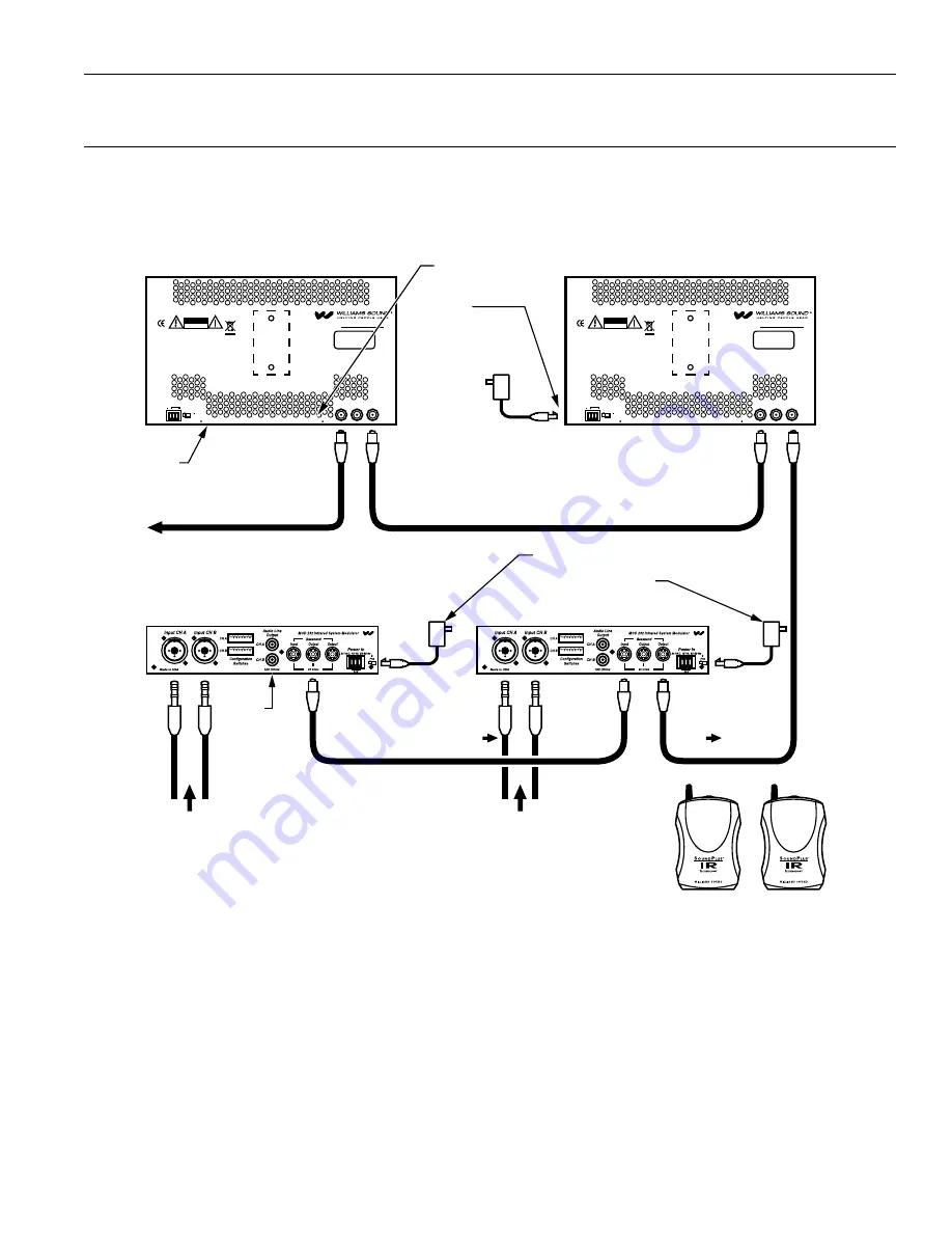
Figure 3: Typical 4-channel configuration when using (2) MOD 232 Modulator, TX9 Emitter, and optional RX22-4 Receivers.
Four-Channel Configuration
WIR TX900, WIR SYS 4
1. Use the WCA 068 short coaxial cable (Figure 3 above) to link the two MOD 232 Modulators.
2. Connect the short coaxial cable to the “Baseband Output” jack of the first MOD 232 in the chain. Connect the other end of the
short coaxial cable to the “Baseband Input” jack of the second MOD 232 in the chain.
3. Each modulator is set-up to accept two audio inputs. When the modulators are linked, they can accept a total of four audio
inputs. Connect the input signals to the audio inputs in the back of the MOD 232 labeled “Input CHA” and “Input CHB.”
Frequencies are pre-set to 2.3, 2.8, 3.3, 3.8 MHz. Frequency selection can be adjusted by using the “Configuration Switches”
located on the back of the MOD 232 (see page 4).
4. Wiring the Modulator to the TX9 Emitter: Connect a coaxial cable to the “Baseband Output” jack of the second MOD 232 in the
chain. The other end of the coaxial cable will connect to the “Baseband Input” jack of the TX9. Additional TX9 Emitters can be
linked together as needed for coverage see Figure 3.


