background image

Specifications - WIR TX90 DC

NOTE:  Specifications subject to change without notice. 

Visit our website for the latest specifications and publications:  www.williamssound.com

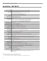
Dimensions, Weight:

11.25” W x 6.25” H x 2.125” D (28.6 cm x 15.9 cm x 5.4 cm), 1.8 lbs (0.8 kg)

Color:

Black with white legends, black acrylic lens (optional white enclosure available)

Power Supply:

Desktop-style, universal power supply.  

Input: 100-240 VAC, 50/60 Hz, 0.6 A.  Line cord specified by country of use.

Output: 24 VDC, 1.0 A, 25 W.  Barrel connector.

50 ft DC power supply extension cable available (WCA 123).

Modulation:

FM Wideband, +50 kHz deviation max., 50 uS pre-emphasis

Carrier Frequency:

Channel A: Selectable, 2.3/3.3 MHz, 

Channel B: Selectable, 2.8/3.8 MHz

Emitter IR Power:

3.5 W

Coverage Area:

30,000 sq. ft. (2,787 sq. m) in single channel mode when using the RX22-4 Receiver

19,000 sq. ft (1,765 sq. m) in two channel mode when using the RX22-4 Receiver

11,000 sq. ft (1,022 sq. m) in four channel mode when using the RX22-4 Receiver

3,350 sq. ft (311 sq. m) in single channel mode when using the RX18 Receiver

Signal-to-Noise Ratio:

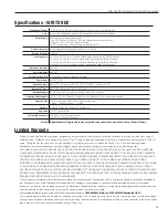
>75 dB, +3 dB 

Frequency Response:

80 to 15,000 Hz, electrical response

Total Harmonic Distortion:

Less than 0.2%, electrical response at 1 kHz

Compression:

Music preset  1:1, Voice preset  1.5:1, Hearing Assist preset 2:1

Auto Carrier Shut-Off:

20 minute timer shuts off carrier when no audio is present

Power Indicator:

Red LED

Audio Volume Level 

Controls:

CH A and CH B Input Level, press to select, 28 dB adjustable range

Audio Indicators:

CH A and CH B Audio Level, yellow LED, flash

Carrier LEDs:

2 green LED carrier “on” indicators

Phones Output:

3.5mm TRS headphone jack. CH A tip, CH B ring on jack, 32 ohm headphone (min)

Application Preset:

Music, Voice, Hearing Assist.  Frequency response;  Music: Flat;  Voice: Mid-range boost;  Hearing Assist: High 

frequency boost

Tone Control:

Press to select, 21 dB adjustable range (1 kHz between low boost/hi-cut and low cut/hi boost).

Power Input:

24 VDC, 0.8 A, 25 W

Audio Input Connector:

CH A and CH  B, 3 wire Phoenix

Input Level:

Balanced or unbalanced, 316 mVRMS (-10 dBV) nominal, 5.7 k Ω input impedance; max input (over volume range) -21 

to +7 dBV.

Baseband Output:

BNC, 50 Ω, for use with TX9 or TX9 DC only

Baseband Cable:

RG 58 Coax, BNC connectors, maximum 1000 ft. (300 m) length

Operating Requirements:

0-50º C (+32 °F to 122 °F) ambient temperature, non-condensing, non-corrosive atmosphere

Mounting Kits:

Wall or Ceiling Mount: BKT 024 Omnidirectional mount.  Optional:  Tripod Stands SS-6.

Warranty:

5 years on transmitter  (90 days on accessories)

Approvals

CE, FCC, RoHS, WEEE

Compatible Receivers:

WIR RX22-4 Four-Channel Receiver

WIR RX18 Two-Channel Receiver

Notes Specifications:  Single end input, volume & tone controls at mid point, 1 kHz, 

“Music” Preset

14

WIR TX9 DC Emitter, WIR TX90 DC Transmitter

Summary of Contents for WIR TX-9 DC

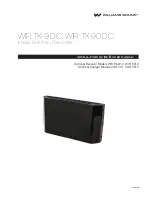
Page 1: ...MAN 209B WIR TX 9 DC WIR TX 90 DC Infrared Emitter and Transmitter Installation Guide User Manual Optional Receiver Models WIR RX22 4 WIR RX18 Optional Charger Models CHG 518 CHG 3512 ...

Page 2: ...one 8 Using the Optional WIR TX9 DC Slave Emitter for Additional Coverage 9 Receiver Safety Information 10 Recycling Instructions 10 Optional Infrared Receivers 11 Optional Chargers 12 Troubleshooting 13 The WIR TX90 DC Power On indicator is not lit 13 The WIR TX90 DC channel A or B On indicator is not lit 13 No sound through receivers 13 Sound through the receivers is weak and noisy 13 Buzzing or...

Page 3: ...ht signals back into audio signals The 2 3 3 8 MHz operating frequencies minimize high efficiency lighting interference No FCC license or radio approval is required with this equipment It can be used anywhere in the world NOTE This equipment has been tested and found to comply with the limits for a Class A digital device pursuant to part 15 of the FCC Rules These limits are designed to provide rea...

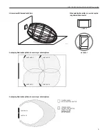
Page 4: ...0 40 50 60 70 80 90 10 20 30 40 50 60 70 80 90 100 110 120 130 140 150 160 FEET FEET RX22 4 RECEIVER RX18 RECEIVER RECEIVER COVERAGE AREA WITH TX9 DC OR TX90 DC TRANSMITTER IN SINGLE CHANNEL MODE A627 Maximum range when using the RX22 4 RX15 2 or RX18 Receiver These patterns are the direct radiation pattern The infrared radiation does not drop to zero outside the illustrated patterns it decreases ...

Page 5: ... WIRTX9 DC WIRTX9 DC WIRTX9 DC A628 Overlapping Illumination patterns to cover Larger Listening Areas WIRTX90 DC COVERAGE AREA WITH SINGLETRANSMITTER COVERAGE AREA WITH SECOND EMITTER ADDED TO SAME EMISSION POINT 50 INCREASE WIRTX9 DC A629 Overlapping Illumination patterns to cover Larger Listening Areas 5 WIR TX9 DC Emitter WIR TX90 DC Transmitter ...
Page 6: ...an be used to extend the DC power connection by 50 ft NOTE The WIR TX90 DC transmits when a baseband signal is present and will shut off after 20 minutes when no baseband signal is present This auto shut off feature preserves the life of the infrared LEDs and reduces power consumption This system is designed for class 2 low voltage wiring Always follow local electrical codes when doing low voltage...

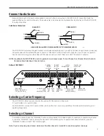
Page 7: ...n Channel A OR the Channel B connector If you choose to operate in two channel mode plug the audio cables with Phoenix connectors in both Channel A AND Channel B connector NOTE By default the WIR TX90 DC is set to operate in two channel mode To turn Channel A or Channel B on off refer to the instructions Selecting a Channel below Selecting a Carrier Frequency The WIR TX90 DC offers two sets of car...

Page 8: ...e input level of both channels simultaneously or independently Make sure the input audio signal is connected to the WIR TX90 DC To adjust the audio input level first activate the channel s you want to adjust by pressing the CHANNEL button then press the VOLUME button The Volume indicator will light Now turn the ADJUST knob clockwise to increase the input signal or counter clockwise to decrease the...

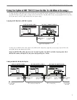
Page 9: ...tter to a WIR TX90 Transmitter TO SECOND TX9 EMITTER TO TX9 EMITTER BASEBAND OUTPUT BASEBAND INPUT WIR TX9 DC EMITTER 2 REAR TO ADDITIONAL EMITTERS TO ADDITIONAL EMITTERS WIR TX9 DC EMITTER 2 REAR WIR TX90 DC TRANSMITTER REAR A622 BASEBAND OUTPUT BASEBAND INPUT BASEBAND OUTPUT BASEBAND INPUT Chaining multiple WIR TX9 DC Emitters Together To add a second WIR TX9 DC emitter panel to the WIR TX90 DC ...

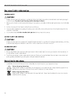
Page 10: ...ease dangerous chemicals cause burns or other serious harm to the user or product PACEMAKER SAFETY CAUTION 1 Before using Williams Sound receivers with a pacemaker or other medical device consult your physician or the manufacturer of your pacemaker or other medical device 2 If you have a pacemaker or other medical device make sure that you are using the Williams Sound receiver in accordance with s...

Page 11: ...eceiver Optional Infrared Receivers A626 ON OFF VOLUME CONTROL DIAL HEADPHONE JACK ON LOW BATTERY SLEEP MODE INDICATOR CHANNEL SELECTOR KNOB Channel Frequency 1 2 3 MHz 2 2 8 MHz 3 3 3 MHz 4 3 8 MHz Model WIR RX22 4 Four Channel Receiver 11 WIR TX9 DC Emitter WIR TX90 DC Transmitter ...

Page 12: ...8 RECEIVER CHARGING INDICATORS CHG 518 FRONT TOP VIEW Multiple Battery Charger Model CHG 518 CHG 518 Back RECEIVER OR TRANSMITTER CHARGING INDICATOR A124 CHG 3512 REAR VIEW DC POWER Figure 16 Multiple Battery Charger Model CHG 3512 12 WIR TX9 DC Emitter WIR TX90 DC Transmitter ...

Page 13: ... if the power and audio input cable are connected to the transmitter and that the WIR TX90 DC Power On and Channel A or B On indicator is illuminated Check to see if the transmitter is connected properly to the sound system The audio level indicators should flash on channels that are selected Make sure the eye is not covered up on the receiver There must be clear line of sight between the receiver...

Page 14: ...et 2 1 Auto Carrier Shut Off 20 minute timer shuts off carrier when no audio is present Power Indicator Red LED Audio Volume Level Controls CH A and CH B Input Level press to select 28 dB adjustable range Audio Indicators CH A and CH B Audio Level yellow LED flash Carrier LEDs 2 green LED carrier on indicators Phones Output 3 5mm TRS headphone jack CH A tip CH B ring on jack 32 ohm headphone min A...

Page 15: ...lar part or term held to be invalid Ifyouexperiencedifficultywithyoursystem callToll FreeforcustomerAssistance 1 800 843 3544 U S A or 19529432252 OutsidetheU S A Your warranty becomes effective the date you purchase your system Your returned warranty card is our way of knowing when your warranty begins It also gives us important information about your system including the serial number This infor...

Page 16: ... 2017 Williams Sound All Rights Reserved 10300 Valley View Rd Eden Prairie MN 55344 800 328 6190 952 943 2252 FAX 952 943 2174 www williamssound com WIR TX9 DC Emitter WIR TX90 DC Transmitter MAN 209B ...

Reviews: