background image

Summary of Contents for AMPETRONIC MLD5

Page 1: ...MLD5 Installation Handbook www ampetronic co www williamsav com...

Page 2: ......

Page 3: ...r other apparatus that produces heat 6 WARNING THIS APPARATUS MUST BE EARTHED GROUNDED 7 Only power cords with the correct power connector may be used to maintain safety Cables incorporating the UK 13...

Page 4: ...ne or line inputs with individually selectable phantom and gain boost For more complex installations you may need ancillary equipment such as microphone pre amplifier s adaptor s for use with 100V lin...

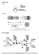
Page 5: ...CONNECTIONS Inputs Outputs 1 Twisted Pair 2 Quad Core Refer to technical specifications for connection details BLOCK DIAGRAM Ampetronic MLD5 Installation Handbook Page 3...

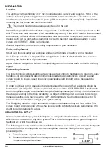
Page 6: ...ion Loops handbook or as per specific design instructions provided by Ampetronic As a result a target current should be known based on achieving acceptable field strength across the area to be covered...

Page 7: ...d by the CH B CURRENT LEDs Headphones can be used with the MONITOR socket to listen directly to the loop current NOTE channel A output appears in the left headphone and channel B in the right If high...

Page 8: ...L CURRENT ADJUSTMENT Screwdriver adjustable control which sets the level of output current delivered to the loop OUTPUT CHANNEL CURRENT LEDs Indicates the peak current delivered to the loop TEMPERATUR...

Page 9: ...ts PHASE SHIFT SELECTOR Selectable 90 phase shift between outputs XLR INPUTS Socket for balanced MIC or LINE signals INPUT GAIN BOOST SELECTOR SWITCH Gain selector ON 15dB INPUT SELECTOR SWITCH Mode s...

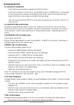
Page 10: ...s are illuminating Check that the CURRENT controls are turned up sufficiently Check the LOOP or TEMP LEDs are not illuminated Ensure the Ear symbol is illuminated and not flashing Check that the loop...

Page 11: ...with a pre installed loop which was designed for use with an old loop driver which might be being replaced Before using this loop ensure that the existing loop will allow the system to perform to an a...

Page 12: ...of unit Unplug the loop and AC power supply from amplifier and replace the failed fuse with the spare fuse in AC power input fuse tray Reconnect the AC power supply and switch on If the fuse fails aga...

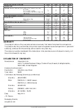
Page 13: ...100 to 5000 4 7 1 24 17 9 6 4 13 0 2 22 100 to 5000 4 7 1 45 32 13 9 2 19 0 2 24 100 to 5000 4 7 1 V A A Hz ms s STATUS SOCKET 2 pin 5mm pitch 90 header The status socket consists of a pair of isolate...

Page 14: ...35 20 90 IP20 0 35 20 90 C WARRANTY This product carries a five year parts and labour warranty from date of shipment from Ampetronic To qualify for the five year warranty the product must be register...

Page 15: ...INSTALLATION NOTES Ampetronic MLD5 Installation Handbook Page 13...

Page 16: ...Contents Copyright Ampetronic Ltd 2013 All rights reserved UP17601 7...

Reviews: