PLA DL210NET Digi-Loop™ DSP Induction Loop Amplifier
14
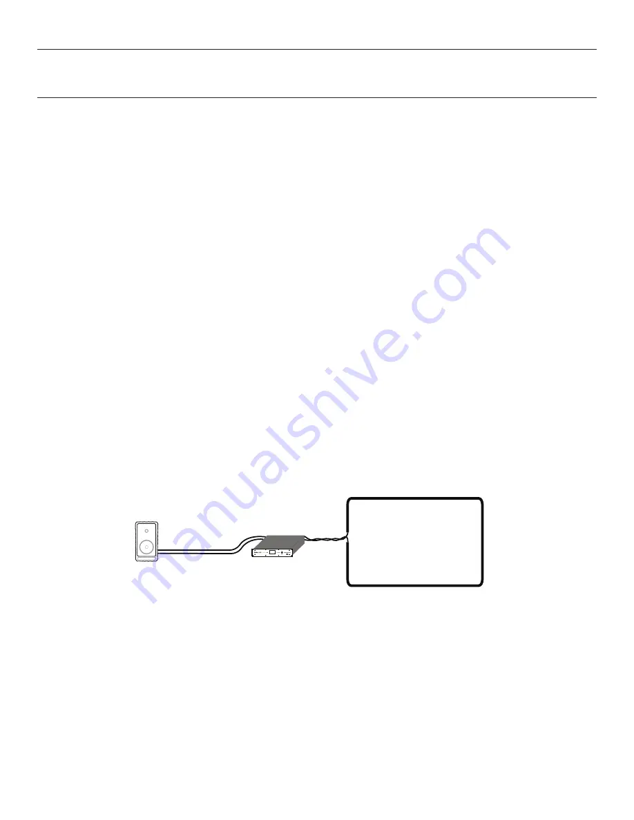
One S Single Loop Calibration using front LCD (Speaker Mode)
1. Define the area needed for the loop layout.
2. Loop and lead in wire DC resistance should be between .5 and 1.5 Ohms.
3. Connect loop wire to the DL210 Phoenix connector and insert to Loop Output B.
4. Turn the power on.
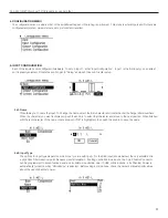
5. Rotate the menu knob clockwise and go to the configuration menu. Push knob to enter and select output configuration and turn
rotary selector to Loop A. Scroll to set-up, click and select loop mode. Select speaker/loop and click to store setting.
6. Going back to the Configuration Menu, select System Configuration page in the menu and select tech tools, then select calibrate.
Scroll down to the frequency, click and select 1 kHz.
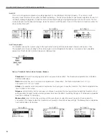
7. With the field strength meter set appropriately, measure the field strength at the mid-point of the loop. Adjust the volume (one step
down in the calibrate page) until the field strength measures 0dB (400m/A) on the field strength meter.
8. This field strength setting should be 3dB at any point within the loop area to meet the IEC 60118-4 standard.
9. Turn the power off.
10. Connect speakers to Output A. Speaker Impedance should not be below 4 Ohms.
11. Turn the power on.
To meet the
IEC 60118 Standard
:
Field strength: 400mA/m audio peak response at 1kHz (Calibration Point)
Frequency response: 100 - 5000Hz ±3dB relative to 1kHz Calibration Point (achieved through Equalization)
Note: The lead length from the amplifier to the loop should be kept as short as possible.
Note: The amplifier must be calibrated to the loop before adjusting the Output Effects.
Figure H: Speaker and Single Loop Concept
A494
Perimeter Loop
Loop Amplifier
Perimeter Loop
Loop Amplifier
Speaker
Perimeter Loop


