PLA DL210NET Digi-Loop™ DSP Induction Loop Amplifier
19
6. OUTPUT CONFIGURATION
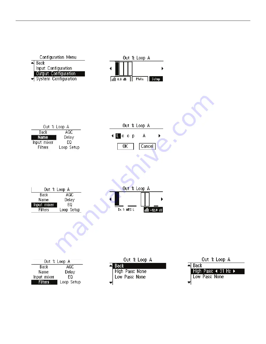
Each of the outputs can be configured individually. To set up Ouput 1, enter “Output Configuration”. Ouput 1 is the first input you can
adjust, so it is already selected. To get to the next input, rotate the knob to the right.
6a. Name
This allows you to name the Output. To change the name, select the first character and rotate the dial to change letters/numbers.
When the character you want is displayed, push the knob in to select that character and move to the next position. When finished
with the last character of the name, rotate knob until “OK” is highlighted; then push the knob in to save the name.
6b. Input Mixer
The Input Mixer provides level adjustment of each of the inputs per each output. This is used when one (or more) input(s) may be
louder or softer than the others. You can use the headphones plugged into the headphone jack to monitor the adjustments.
6c1-2. Filters
Filters provide adjustment for a high pass filter and low pass filter crossover frequency.
The High Pass Filter has crossover points at: Off (None), 31Hz, 62 Hz, 125 Hz, and 500 Hz.
The Low Pass Filter has crossover points at: Off (None), 16 kHz, 8 kHz, and 6.3 kHz.


