background image

PLA DL210NET Digi-Loop™ DSP Induction Loop Amplifier

8

Typical Connections 

Figure C: Example Connections


INDUCTION LOOP

#2

INDUCTION LOOP

#1

ROUTER

iPAD, ANDROID TABLET, 

OR PHONE WITH WI-FI

COMPUTER

(HARD-WIRED TO ROUTER)

BI-DIRECTIONAL CONTROL/FEEDBACK

LEGACY THIRD-PARTY CONTROLLER

(AMX, CRESTRON, ETC.)

DIGITAL AUDIO 

FROM MIXER, PREAMP, ETC.

ANALOG AUDIO 

FROM MIXER, PREAMP, ETC.

UNBALANCED AUDIO  FROM CONSUMER-

GRADE PRODUCT SUCH AS CD PLAYER or 

MP3 PLAYER

FROM COMMERCIAL

SPEAKER SYSTEM

TO RECORDING

EQUIPMENT

LAPTOP (FOR INITIAL CALIBRATION/CONFIGURATION)

PLA DL210NET

PROFESSIONAL INDUCTION LOOP AMPLIFIER WITH DIGITAL SIGNAL PROCESSING

A434

Summary of Contents for PLA DL210NET

Page 1: ...PLA DL210NET Digi Loop DSP Induction Loop Amplifier USER Manual MAN 179C ...

Page 2: ...oop Concept 11 Dual Loop Calibration using front LCD Dual Loop Mode 12 Figure F Dual Loop Concept 12 Phased Array Calibration using front LCD Phased Array Mode 13 Figure G Phased Array Concept 13 One Speaker Single Loop Calibration using front LCD Speaker Mode 14 Figure H Speaker and Single Loop Concept 14 Front Screen Menu Tree 15 Figure I Front Screen Menu Tree 15 Front Menu Detail 16 1 LOOP STA...

Page 3: ...d Password Timeout 23 7f1 2 Power Save Auto Sleep Threshold 23 7g Tech Tools 24 7g1a c Calibrate Output Frequency Volume 24 7g2 Loop Test 24 7g3 Version 24 7g4 Device Name 25 7g5 IP Address 25 7g6 Amp Temp 25 7g7 Reset All 25 PC Application Initial Setup 26 Figure J Application Settings Window 26 Using the PC Mixer Application 27 Figure K PC App Toolbar 27 Figure L PC App Main Screen 28 Figure M I...

Page 4: ...ll near any heat sources such as radiators heat registers stoves or other apparatus including amplifiers that produce heat 9 Do not defeat the safety purpose of the polarized or grounding type plug A polarized plug has two blades with one wider than the other A grounding type plug has two blades and a third grounding prong The wide blade or the third prong is provided for your safety If the provid...

Page 5: ...l Rear Panel A label located at the rear panel power connection indicates the AC power input for the unit The label will read 100 240V AC 50 60Hz 210W Auto switching 3 Do Not Plug in the input output ethernet USB or RS 232 connections while the power switch is switched to the ON position 4 Do Not Touch the PLA DL210NET with wet hands Do not handle the PLA DL210NET or power cord when your hands are...

Page 6: ... crisp clear audio making speech more intelligible to the listener The system technician has control over Mixing Equalization Compression Ratio Phase and Frequency shaping parameters High current output means good powerful broadcast and listener reception regardless of position in the room Features DSP Audio Processing Digital XLR Input LCD Screen with Metering Ethernet RS 232 and USB control Mixi...

Page 7: ... JACK LINE INPUTS RCA COOLING FAN LINE OUTPUTS POWER AND FUSE ACCESS A432 INDUCTION LOOP SPEAKER OUTPUTS SPEAKER LEVEL INPUTS HEADPHONE JACK Figure B Rear Panel ETHERNET JACK MENU GUI DISPLAY MENU CONTROL KNOB MIC LINE INPUTS AES EBU XLR JACK RS 232 JACK USB JACK LINE INPUTS RCA COOLING FAN LINE OUTPUTS POWER AND FUSE ACCESS A432 INDUCTION LOOP SPEAKER OUTPUTS SPEAKER LEVEL INPUTS HEADPHONE JACK ...

Page 8: ...R BI DIRECTIONAL CONTROL FEEDBACK LEGACY THIRD PARTY CONTROLLER AMX CRESTRON ETC DIGITAL AUDIO FROM MIXER PREAMP ETC ANALOG AUDIO FROM MIXER PREAMP ETC UNBALANCED AUDIO FROM CONSUMER GRADE PRODUCT SUCH AS CD PLAYER or MP3 PLAYER FROM COMMERCIAL SPEAKER SYSTEM TO RECORDING EQUIPMENT LAPTOP FOR INITIAL CALIBRATION CONFIGURATION PLA DL210NET PROFESSIONAL INDUCTION LOOP AMPLIFIER WITH DIGITAL SIGNAL P...

Page 9: ...plifier and controller to the network Note A standard ethernet cable is terminated with either T568A pinout on both ends or T568B pinout on both ends A crossover cable has T568A pinout on one end and T568B pinout on the other end See the internet for more information on terminating ethernet cables RS 232 Cable Wiring This is required if the third party controller Crestron AMX Extron etc only has R...

Page 10: ...ops repeat step 12 for Loop B 14 If calibrating a Phased Array observe the Average Current level in the calibrate window for Loop A Click on the Loop A button to switch to Loop B in the Calibrate Window and turn the offset up until the average current for Loop B matches what you observed for Loop A Click on the Loop B button to observe the current for both loops they should be close Go to step 16 ...

Page 11: ... 1 kHz 8 With the field strength meter set appropriately measure the field strength at the mid point of the loop Adjust the volume one step down in the calibrate page until the field strength measures 0dB 400m A in the center of the looped area 9 This field strength setting should be 3dB at any point within the loop area to meet the IEC 60118 4 standard 10 Back out of calibrate system configuratio...

Page 12: ...field strength measures 0dB 400mA m 9 Rotate the menu knob clockwise and go to the configuration menu Push knob to enter and select output configuration and turn rotary selector to Loop B Scroll to set up click and select loop mode Select dual loop and click to store setting 10 Going back to the Configuration Menu select System Configuration page in the menu and select tech tools then select calib...

Page 13: ...ets 400mA m using the field strength meter at the center of the looped area The current in the Master A should be measured and then duplicated for the slave loop B 6 Connect the Slave Loop wire to the DL210 Phoenix connector and connect to Loop Output B Adjust the current into Slave loop to match the Master Loop 7 Turn the power off 8 Connect all inputs to be used into the DL210 9 Turn the power o...

Page 14: ...7 With the field strength meter set appropriately measure the field strength at the mid point of the loop Adjust the volume one step down in the calibrate page until the field strength measures 0dB 400m A on the field strength meter 8 This field strength setting should be 3dB at any point within the loop area to meet the IEC 60118 4 standard 9 Turn the power off 10 Connect speakers to Output A Spe...

Page 15: ...ed LPF MBPF HPF High Pass Lo Mid Hi Presets RS 232 Network LCD Security Power Save Baud Rate Data Format Static IP IP Address Subnet Gateway Telnet Port Backlight Delay Brightness Set Password PW Timeout Threshold Tech Tools Calibrate Calibrate Frequency Auto Sleep Metal Comp Volume Version Device Name IP Address Amp Temp Reset All Load Preset Save Preset Change Name Advanced High Pass Mode Preset...

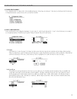
Page 16: ...ONE MONITOR The Headphone monitor can be used to listen to any individual source or output or to listen to adjustments as they are made in the menu Rotate the knob once to the right to see the Headphone Monitor screen The vertical bar going through the bar graph represents a reference level of 0dB You can change the volume of the headphones or mute the audio from this screen To change the headphon...

Page 17: ...racter and rotate the dial to change letters numbers When the character you want is displayed push the knob in to select that character and move to the next position When finished with the last character of the name rotate knob until OK is highlighted then push the knob in to save the name 5a2 Input Type The options for input type depend on which input you are setting up For the AES input shown be...

Page 18: ...atio Attack Release and Makeup Gain 5a4a e Threshold Ratio Attack Release Makeup Threshold is the level of incoming signal at which compression takes effect The Threshold is adjustable from 96 0dB to 0 0dB in 0 5dB steps Ratio determines how much compression is applied when it takes effect The Ratio is adjustable from 1 0 1 no compression to 10 0 1 in 0 1 steps Attack is the speed at which compres...

Page 19: ...ect that character and move to the next position When finished with the last character of the name rotate knob until OK is highlighted then push the knob in to save the name 6b Input Mixer The Input Mixer provides level adjustment of each of the inputs per each output This is used when one or more input s may be louder or softer than the others You can use the headphones plugged into the headphone...

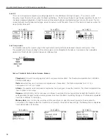
Page 20: ...stable and the Minimum Level also called Threshold is internally set relative to the calibration target level and is not adjustable The calibrated target level is set in Tech Tools Calibrate and this is the level the AGC will attempt to hold Hold Time is how long the gain is maintained on signal when the automatic gain settings take effect In the Custom preset the Hold Time is adjustable from 1 se...

Page 21: ...12 dB To review or change the pole frequencies see 6f4a d Advanced Settings below 6f4a d Advanced Settings Lo Mid Hi Metal Comp Advanced Settings provide the ability to change the frequency point define a more specific numerical dB level or adjust for high frequency metal loss The Lo Mid and Hi filters can all be adjusted from 20 Hz to 20kHz and 12 dB to 12 dB The Metal Compensation can be adjuste...

Page 22: ...ets are available as a starting point with defaults as shown Dual Loop Phased Array and Speaker Loop There are also three Custom Presets available User 1 User 2 and User 3 The User Presets can be renamed The Dual Loop Phased Array and Speaker Loop Presets cannot be altered or saved they can only be loaded We recommend saving the settings in a User Preset in case of power outage or other catastroph...

Page 23: ...period or always off The backlight delay determines how long before the auto dim or auto off function takes effect Note that the LCD continues to display information when the backlight is off The brightness of the backlight can be adjusted from 1 10 7e1 2 Security Set Password Password Timeout The Security function allows you to set a password and determine the password timeout delay The 3 digit a...

Page 24: ...B Frequency of the test tone can be set to 100 Hz 500 Hz 1 kHz 2 5 kHz or 5 kHz Volume of the test tone can be adjusted from 96 dB to 0 dB in 1 dB steps 7g2 Loop Test The Loop Test option performs an open circuit test to verify that a loop is connected If it finds that a loop is open the test will show FAIL Note that when running a single loop in dual loop mode a FAIL is acceptable for the output ...

Page 25: ...red here A zz by the temperature means that the amplifier is in sleep mode see 7f Power Save for how to adjust when the amplifier goes to sleep 7g7 Reset All This resets all of the settings back to factory defaults Any user entered information will be lost The amplifier may need to be rebooted after the factory reset is performed to change states For example if the amplifier goes to sleep it may s...

Page 26: ...l be controlling the amplifier unzip the file then double click on the PLA DL210 Mixer Windows Installer Package icon to install the PC Mixer App 3 Connect the Ethernet cable between the Loop Amplifier and the Computer If on a network standard ethernet cables can be used When connecting a computer directly to the amplifier using the ethernet connection a crossover cable is required 4 Open the PC M...

Page 27: ...ne generator The calibration window provides a convenient way to calibrate the loop by generating a test tone adjusting the frequency and output level and measuring the signal level of the loop with a field strength meter Note The field strength meter can be purchased through Williams Sound model PLM FSMP Please see our website for more information Full Screen View This returns to a full screen vi...

Page 28: ... Name Provides the ability for a custom name The jack label is preserved above the custom name Loop Modes Changes the internal configuration of the amplifier to drive the load s chosen Use Dual Loop mode for a single loop Input Output Overload Indicators This light will turn red once an overload condition is reached It remains red until cleared Clear the overload indicator by clicking on it Status...

Page 29: ...k is the speed at which compression reacts to get to the target level The Attack is adjustable from 2ms to 500ms in 2ms steps Release controls the time that the compressor continues to work after the input signal drops beneath the threshold Short settings release the signal quickly while long release times have the effect of sustaining the signal The Release is adjustable from 10ms to 2500ms in 10...

Page 30: ...ain the gain level when the speaker pauses or stops talking For Music shorter hold times are often used since the signal tends to be continuously present Attack is the speed at which the gain is boosted when the level of the input signal crosses into the Level window Short settings react to the signal quickly while long attack times have a lagging effect When the speaker pauses too short of an att...

Page 31: ...r to the section Setup and Calibration Procedure using a laptop or windows tablet When calibrating a Phased Array after Loop A has been calibrated with the field strength meter switch to Loop B and adjust the Offset for Loop B until the Average Current for Loop B matches the average current for Loop A Figure P Figure P Calibration Window Phased Array Mode shown Average current delivered to Loop A ...

Page 32: ... inputs 1 2 4dBu Balanced or Unbalanced Loop Outputs 2x Phoenix Terminal Block Required Loop Resistance 0 5Ω to 1 5Ω DC Output Current Loop One Loop Output A or B 12A rms Two Loops Outputs A and B 10A rms each Output Power Speaker 50 Watts X 1 Channel 4 Ω 35 Watts 8 Ω Class D Loop Frequency Response 100Hz to 10kHz 400mA Output A or B Speaker Frequency Response 20Hz 20kHz Output A Speaker Dynamic R...

Page 33: ...on set correctly Turn the loop system off and check to see if background noise remains If it does the noise may be created by other electrical systems and picked up by the loop Turn off nearby appliances to find the source of the interference If a microphone is connected to the microphone input try shutting off the microphone or unplugging it If the noise goes away turn it back on and try reducing...

Page 34: ... or modified by anyone other than a factory authorized service technician Warranty does not cover normal wear and tear on the product or any other physical damage unless the damage was the result of a manufacturing defect Williams Sound is not liable for consequential damages due to any failure of equipment to perform as intended Williams Sound shall bear no responsibility or obligation with respe...

Page 35: ...PLA DL210NET Digi Loop DSP Induction Loop Amplifier 35 Notes ...

Page 36: ...10300 Valley View Rd Eden Prairie MN 55344 800 328 6190 952 943 2252 FAX 952 943 2174 MAN 179C www williamssound com ...

Reviews: