background image

Summary of Contents for GRAVITY 1403611

Page 1: ...formation consult a qualified installer service agency or the gas supplier WARNING Do not install any of these fur naces Natural or L R Gas in mobile homes trailers or recreational vehicles WARNING If...

Page 2: ...DIRECTLY OR INOIRECT LY FROM ANY DEFECT IN THE PRODUCT OR ANY COMPONENT OR FROM THE USE THEREOE THE REMEDIES SET FORTH HEREIN ARE THE EXCLUSIVE REMEDIES AVAILABLE TO THE USER AND ARE IN LiEU OF ALL O...

Page 3: ...2203621 2203622 3003621 and 3003622 are equipped with a wall thermostat Optional Accessories MODELS 1403611 1403612 1403621 1403622 For walls greater than 9 inches thick and up to 24 inches thick use...

Page 4: ...UE TO HIGH TEMPERATURES locate the furnace out of traffic and away from furniture and draperies ALERT children and adults to the hazards of high sur face temperature and to keep away to avoid burns or...

Page 5: ...r for bath tub use as most contain fillers and will not withstand high temperatures Pipe joint compound resistant to L IR Gases Electrical wiring supplies as needed for optional blower if equipped see...

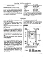
Page 6: ...a door or draperies Do not put in a closet alcove hallway or other confined space 7 Be sure that gas piping and electrical wiring optional blower only can be brought to the furnace See sec tions on g...

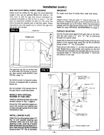
Page 7: ...Use a stud Iocator or small finishing nails Repeatedly drive and remove a nail into the wall in the area of the stud until you find it Then find one side Leave the nail there Drive another nail just...

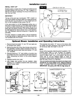
Page 8: ...port legs using four 4 8 roundhead long screws F Fig 5 provided Push the air inlet shield J on from the exterior side of wall Rotate the air inlet shield until notches on the end of the tube are strad...

Page 9: ...ion shown and fasten to inner cas ing through pre punched holes with screws C and D provided 3 Remove knock out G from bottom of junction box and install 115V line in accordance with local electrical...

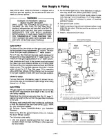
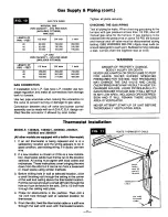
Page 10: ...st be of adequate size to handle the BTU HR requirements and length of the run for the unit being installed Determine the minimum pipe size from Fig 10 page 11 basing the length of the run from the ga...

Page 11: ...CIFIED PRESSURES FOR TESTING HIGH PRESSURES MAY DAMAGE THE GAS VALVE AND CAUSE OVER FIRING WHICH MAY RESULT IN HEAT EX CHANGER FAILURE LIQUID PETROLEUM L P GAS IS HEAVIER THAN AIR AND IT WILL SE I FLE...

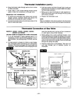
Page 12: ...tat is being replaced and is in a satisfactory location and the wiring appears to be in good condition use existing wiring If in doubt use new wire 2 If a new location is chosen or if this is a new in...

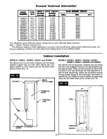
Page 13: ...termined under con tinuous operating conditions and was determined independently of any installed system Cabinet Installation MODELS 1403612 1403622 1403611 and 1403621 Set cabinet over furnace body d...

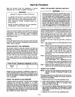
Page 14: ...provided in the gas valve to facilitate measuring the manifold gas pressure A U Tube manometer having a scale range from 0 to 12 inches of water should be used for this measurement The manifold press...

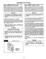
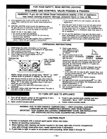
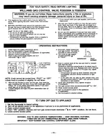
Page 15: ...ND OPERATING INSTRUCTIONS and use a match to light the pilot as instructed WARNING DANGER OF IGNITION FLASH AND EYE INJURY OR BLINDNESS PROTECT YOUR EYES NEVER ATTEMPT TO LIGHT PILOT WITH GAS CONTROL...

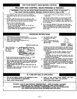
Page 16: ...TOP 12 Follow B in the safety information above If you don t smell gas go to the next step 7 Loosen wlngnut and open pilot observation door if 13 equipped 14 8 Find pilot follow metal tube from gas co...

Page 17: ...e 5 minutes to clear out any gas then smell for gas including near the floor If you then smell gas STOPI Follow B In the safety information above If you don t smell gas go to the next step 6 Loosen wl...

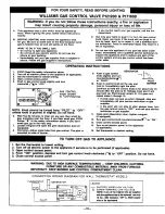
Page 18: ...ll for gas including near the floor If you then smell gas STOP Follow B in the safety information above If you don t smell gas go to the next step 7 Loosen wingnut and open the pilot observation door...

Page 19: ...KNOB SHOWN POSITION NOTE Knob cannot be turned from PILOT to OFF unless knob is pushed in slightly Do not force 6 Wait five 5 minutes to clear out any gas then smell for gas including near the floor I...

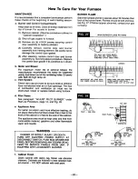
Page 20: ...e about 10 minutes then look at the burner flame Flames should be soft and blue see Fig 27 If flames appear abnormal contact your gas company MAIN BURNER FLAME PATTERN 1111111111 Ill llll tlltl TOO MU...

Page 21: ...of valve with pilot burning and thermostat contacts closed Should be 140 millivolts or more Remove thermostat lead wires from valve terminals If pilot now stays lit trace thermostat wiring circuit for...

Page 22: ...d to back of control valve B Temperature dial out of See valve manufacturer s instruction calibration Bulb control model C Bulb or capillary broken Replace valve Bulb control model D Thermostat wiring...

Page 23: ...NO 1 2 3 4 5 NOTE USE ONLY MANUFACTURE S AUTHORIZED PARTS 6 7 8 9 10 PART NO 6A24 6B33 P321017 P129700 6A23 P130600 6A93 P128400 P130700 6B64 DESCRIPTION SWITCH BRACKET SWITCH BOX SWITCH PULL CHAIN S...

Page 24: ...CK WALL 8A85 FLUE EXTENSION MAX 9 THICK WALL BB64 MOUNTING SPACER PLATE P121800 AIR INLET GASKET VENT A FLUE EXTENSION 15 INCH WITH 1 P147001 GASKET EXTENSION KIT _ AIR INLET COLLAR 15 INCH WITH 1 P14...

Page 25: ...Williams Direct Vent Gas Fired Wall Furnace REPLACEMENT PARTS FOR MODELS 1403611 140361 2 1403621 1403622 FOR PARTS lISTING SEE PAGE 24 USE ONLY MANUFACTURER S AUTHORIZED PARTS 25 1...

Page 26: ...motor is noisy Housing rattling Blower dirty Blower wheel bent Reset thermostat to desired setting Check pilot Relight if necessary follow ing instructions for Operating Your Furnace If gas valve is...

Reviews: