PMP-098
Oil Furnaces
–
Furnace Manual
6
11/13
1.6.1.
Masonry chimney
This furnace can be vented into an existing masonry chimney.
However, the unit must not be vented into a chimney into which a
solid fuel burning furnace is already being vented.
Before venting this furnace into a chimney, its condition must be
checked and repairs made, if necessary. Also, the chimney lining
and dimensions must conform to local and national codes.
1.6.2.
Factory Built Chimneys
Oil fired furnaces are approved for use with “L” type vents. The unit
may also be used with an approved chimney of proper dimensions
and temperature ratings as specified in the installation code. Refer
to chimney manufacturer’s instructions for proper installation.
1.6.3.
Draft Regulator
It is recommended that a draft regulator be installed in cases where
the draft is either high or variable due to external conditions. Follow
the instructions provided with the regulator.
1.6.4.
Side-wall Venting
The heating unit is approved for side-wall venting. This system is
comprised of a model VTK-54 side-wall venter and a 4” insulated
vent pipe, model IFV-410, IFV-420. Refer to the installation
instructions provided with the venting system.
1.7.
BLOCKED VENT SHUT-OFF DEVICE
(BVSO) FOR CHIMNEY VENTING -
OPTIONAL
It is imperative that this device be installed by a
qualified service technician.
A positive pressure venting system (Sealed
Combustion System or Direct Vent) must NOT use
the BVSO. Follow the instructions supplied with
the venting system.
This device is designed to detect the insufficient evacuation of
combustion gases in the event of a vent blockage. In such a case
the thermal switch will shut down the oil burner. The device will then
need to be re-armed MANUALLY.
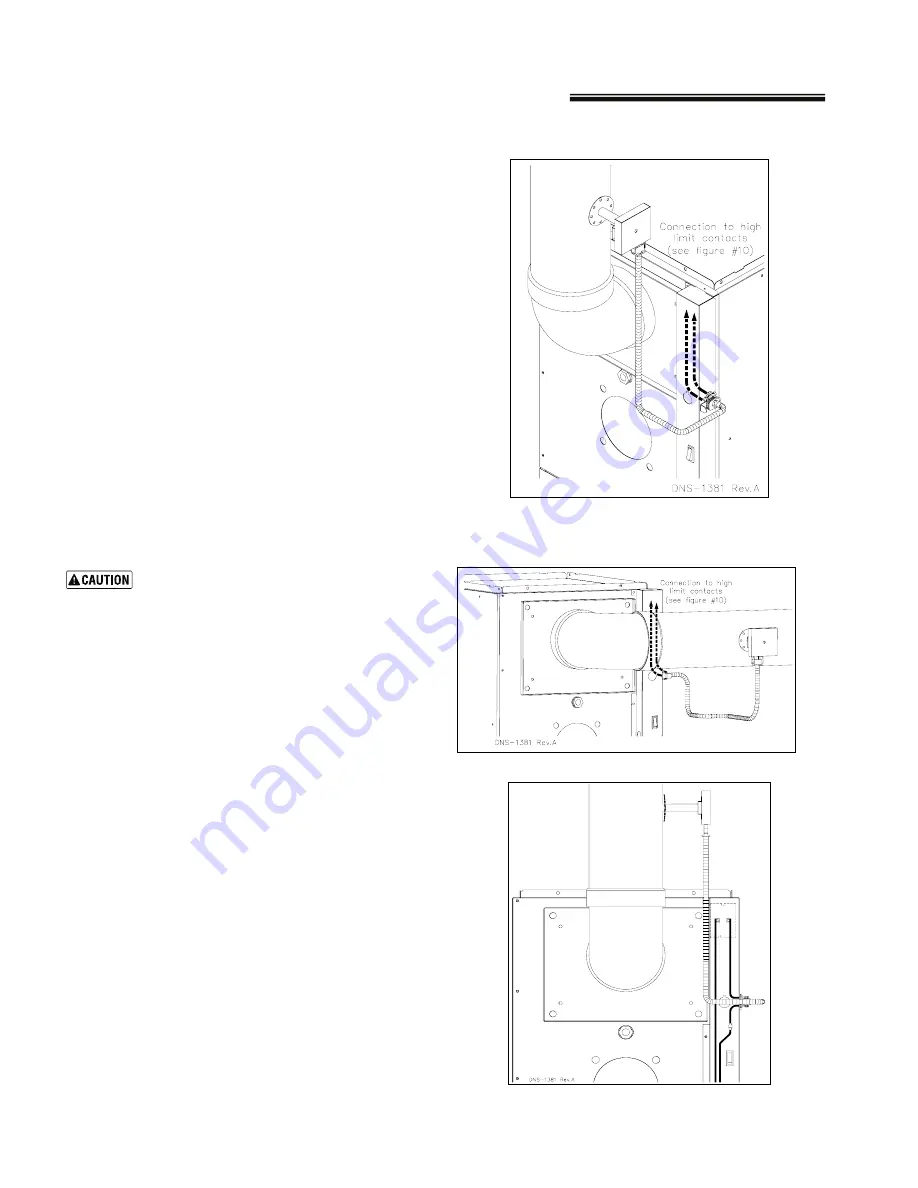
Refer to the detailed instructions and wiring diagrams supplied with
the BVSO for the installation and wiring procedures. The length of
wires supplied with the unit is such that the safety device must be
installed between the flue outlet of the appliance and the draft
regulator, as indicated in the instructions.
It is also essential that the BVSO be maintained annually. For more
details refer to the instructions supplied with the device itself, as well
as Section 2 of this Manual.
1.7.1.
BVSO Performance Test
(If installed)
The purpose of the following test is to check that the electrical outlet
on the furnace, designated to the BVSO, is functional.
1.
Start up the burner;
2.
Disconnect one wire of the BVSO;
3.
The burner must shut-off immediately, while the blower
continues to run to the end of the cool-down cycle.
If the test is not in line with the above, call a QUALIFIED SERVICE
TECHNICIAN.
Figure 8: BVSO mounting installation: Upflow with
vertical exhaust (OPTIONAL)
Figure 9: BVSO mounting installation: Upflow with
horizontal exhaust (OPTIONAL)
Figure 10: BVSO Wiring (OPTIONAL)


