SCH & SCL
Oil Furnaces
–
Furnace Manual
670-000-006-1007
5
Connect fuel oil piping
General oil piping requirements
•
Location and installation of oil tanks, oil piping and burners
must follow:
•
NFPA 31, Standard for the Installation of Oil-Burning
Equipment.
•
In Canada, CSA B139, Installation of Oil-Burning
Equipment.
•
Local codes and regulations.
•
Information provided with burner and fuel pump.
•
If any part of fuel oil tank is above level of burner, an anti-
siphon device must be used to prevent flow of oil in case of
oil line break.
•
Support oil lines as required by codes.
•
Make tank connections with swing joints or copper tubing to
prevent breaking in case the tank settles. Make swing joints
so they will tighten as tank settles. Non-hardening pipe joint
compounds should be used on all threads.
Do not use Teflon tape as an oil pipe sealant. It
can cause valves to fail, creating hazards. Use
only flare fittings. Do not use compression fittings.
Failure to comply could result in severe personal
injury, death or substantial property damage from
oil leakage and/or fire hazard.
•
Underground pipe must be run in a casing to prevent oil
leaking into ground or under floor. Check local codes for
information.
Oil piping connection at burner
•
Connect oil line to burner using a flare fitting.
Use of any connection other than a flare fitting at
the oil connection to the burner could result in a
fuel oil leak, with the potential for severe personal
injury, death or substantial property damage.
•
See local codes for appropriate arrangement and piping of
filter, control valves, etc. connecting to oil tank.
•
Refer to burner manual for oil system requirements. Verify
that suction lift does not exceed stated limit. Where lift
exceeds limit for a one-pipe system, use a two-pipe system
as directed in burner manual.
Electric shock hazard. Can cause severe
personal injury or death if power source, including
service switch on furnace, is not disconnected
before installing or servicing.
6
Wire furnace & burner
Wire burner
The burner harness is factory-wired to the furnace at the factory.
Plug the burner harness into the mating burner connector to wire
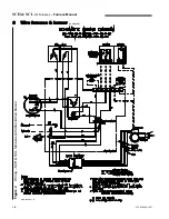
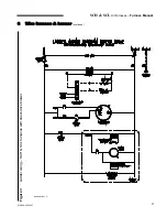
the burner. Refer to the wiring diagram on pages 16 and 17 for
further information.
Install and wire thermostat / shut-off
system
Mount the room thermostat on an interior wall in the natural
circulating path of room air. Do not locate the thermostat so it is
exposed to cold air infiltration, drafts from windows or doors, air
currents from supply or return air registers, behind obstructions,
on a shelf, in a closet, or in a corner.
Ensure that the thermostat will not be exposed to heat from a
nearby fireplace, radio, television, lamp or rays from the sun. Do
not mount the thermostat on a wall over a supply or return duct,
chimney or vent.
WARNING
Wire thermostat to the vent terminal pressure switch and to the
furnace electrical box (refer to wiring diagram). Set thermostat
anticipator as shown on wiring diagrams on pages 16 and 17.
Connect power wiring
All wiring must conform to:
•
National Electrical Code, ANSI/NFPA 70, latest edition and
any additional national, state or local codes.
•
In Canada, CSA C22.1 Canadian Electrical Code Part One
and any local codes.
•
Wiring must be N.E.C. Class 1. If original wire as supplied
with furnace must be replaced, type 105° C wire or equivalent
must be used. Supply wiring to furnace must be sized for the
load required (see Section 12).
•
Provide electrical ground at furnace as required by codes.
Connect 120 VAC/60 Hertz, single phase separate electrical line
from the main house panel to the power leads in the furnace
electrical box as shown on wiring diagram, pages 12, 13, 14 and
15. Provide a fused disconnect in the power wiring, following all
local codes.
Ensure the wire size and type are adequate for the electrical load
(see Section 12 and furnace nameplate for value).
Limit control
The furnace is equipped with a fan switch/limit control. This
control limits the air leaving the heat exchanger to 200° F or less.
The fan switch continues fan operation until the air drops to a
preset temperature. For most installations, set the blower ON
setting at 110° F and blower OFF setting at 90° F. If a longer cool
down period is desired, lower the OFF setting.
WARNING
WARNING
15
Summary of Contents for SCH High Boy
Page 12: ...SCH SCL Oil Furnaces Furnace Manual 12 670 000 006 1007...
Page 13: ...SCH SCL Oil Furnaces Furnace Manual 670 000 006 1007 13...
Page 14: ...SCH SCL Oil Furnaces Furnace Manual 14 670 000 006 1007...
Page 25: ...SCH SCL Oil Furnaces Furnace Manual 670 000 006 1007 COMPONENTS AND REPLACEMENT PARTS 25...
Page 39: ...SCH SCL Oil Furnaces Furnace Manual 670 000 006 1007 X40132 Rev D 39...


