SCH & SCL
Oil Furnaces
–
Furnace Manual
670-000-006-1007
4
Venting – Sealed Combustion System
Failure to follow all instructions can result in flue gas
spillage and carbon monoxide emissions, causing
severe personal injury or death.
The furnace can be side-wall vented without the use of a side-wall
power vent, using a venting system with the high static pressure
Beckett AFII and Riello 40-BF oil burners. Outdoor combustion air
must be directly connected to the burner or the venting system will
not function..
The notable characteristics of the vent system are as follows:
a)
Certified for use of the following materials for ducting the intake
air from the terminal to the burner: Schedule 40 PCV DWV,
Schedule 40 ABS DWV and ASTM D-2729 sewer pipe;
b)
One hole of minimal size (6 inches) is required to be cut into
the side-wall and the terminal is designed to fit through a
minimum 2 x 8 joist space.
c)
Incorporates a vent blockage safety shutdown system. If the
vent or intake opening ever becomes partially or fully blocked,
the burner will shut down before a #1 smoke condition occurs;
d)
The intake vent circuits within the terminal can be accessed for
cleaning.
There are three main components to the venting system:
- Vent terminal kit VTK-1 for the 105 series models or VTK-2 for the
160 series models.
- Flexible insulated venting material for IFV3 for the 105 series
models or IFV4 for the 160 series models
- Field supplied 3 inch PVC or ABS intake piping.
Poisonous carbon monoxide gas hazard.
Even though the flexible venting is insulated, it must
not run through an unheated space.
To do so can cause residual condensation inside the
stainless steel liner, which may eventually perforate
the liner and allow vent gases to enter the dwelling,
which can result in personal injury and/or death or
property damage.
Insulated flexible venting
The certified venting materials come in 3 lengths, Model # IFV3-15,
IFV3-23 and IFV3-30 for the 105 model series or IFV4-15, IFV4-23
and IFV4-30 for the 160 model series, correspond to 15, 23 and 30
feet of continuous lengths of vent. The vent construction is coaxial
and incorporates a stainless steel corrugated, flexible liner,
surrounded by a thick insulation blanket and covered with an outer
layer of flexible corrugated aluminum sleeve to protect the insulation.
Splicing vent lengths together is prohibited.
The maximum and
minimum continuous vent lengths permitted for installation are:
5 feet minimum
30 feet maximum
Side-wall venting installation
Cut and abrasion hazard.
Always wear protective gloves and eye protection
when handling the vent material.
The process of cutting and fitting the flexible vent
material exposes the installer to sharp edges that can
cause severe cuts to the skin.
Connection to the furnace breach
WARNING
1.
Determine in which direction the venting will be routed from the
furnace;
2.
The flexible venting has 4 pieces of corrugated spin sleeve that
has been temporarily screwed over top of it. Remove the spin
sleeve completely by unscrewing it in a counter-clockwise
direction;
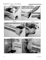
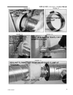
3. Using tin snips, cut the aluminium outer sleeve back by 5
inches on the IFV Series vent (see Figure 1.1). Ensure the
snips are well adjusted and sharp or the cut end of the venting
will be too jagged to start the threads of the spin sleeve (see
Figure 1.1).
4.
Prepare the furnace breach end of the insulated flex vent by
first screwing the spin sleeve onto the corrugated aluminum
jacket (see Figure 1.2) until the trailing edge of the spin sleeve
is about 12 inches from the end of the vent (see Figure 1.3).
5.
Pull the insulation back to expose the corrugated stainless steel
core.
6.
Cut the corrugated stainless steel core back by 3 inches on the
IFV Series vent. You should now have about 3 inches of
insulation hanging out past the stainless steel core (see Figure
1.4);
7.
Push the stainless steel core onto the breach pipe as far as it
will go (see Figure 1.5) and mechanically attach the vent to the
breach using three of the #8 x 1/2
"
self-drilling screws provided
with the VTK Series kit. The screws should be equally spaced
around the circumference of the stainless steel core, starting
with the first screw at top dead center. Start the drill point of the
screws in the valleys of the corrugations at 3/8
"
-5/8
"
back from
the end of the stainless steel core, so the screw heads can be
properly sealed in the forthcoming operations (see Figure 1.6);
8.
With the stainless steel core now firmly attached to the breach,
apply sealant all around the joint, where the corrugated
stainless steel core meets the smooth outer surface of the
breach pipe (see Figure 1.7). In other words, the sealant must
be centered over the joint;
WARNING
9. Also, make sure that the heads of the self-drilling, stainless
steel screws are completely covered with the sealant;
10. Two stainless steel band clamps are provided with the VTK
Series kits. Position one stainless steel band clamp over the
sealant, so that the edge of the clamp closest to the breach
lines up with the sealant that is closest to the breach. Ensure
that the band will close with an action of one strip sliding over
the other - not under the gear head of the draw clamp (see
Figure 1.8). Tighten the band clamp with considerable torque to
cause the sealant to be squeezed into all crevices and to ooze
out of the edge of the clamp closest to the breach (see Figure
1.9);
11. The seal is permanent and should never need to be broken,
since the breach plate can be removed for cleaning and
inspection using the 4-bolt joint;
12. Tuck the vent insulation into the breach collar;
13. Screw the spin sleeve tightly into the breach collar for a finished
appearance. Wrap the other end of the spin sleeve with
aluminum tape to cover any metal burrs that may be present
(see Figure 1.10);
14. Bend the venting into the desired radius coming off the breach.
WARNING
9
Summary of Contents for SCH High Boy
Page 12: ...SCH SCL Oil Furnaces Furnace Manual 12 670 000 006 1007...
Page 13: ...SCH SCL Oil Furnaces Furnace Manual 670 000 006 1007 13...
Page 14: ...SCH SCL Oil Furnaces Furnace Manual 14 670 000 006 1007...
Page 25: ...SCH SCL Oil Furnaces Furnace Manual 670 000 006 1007 COMPONENTS AND REPLACEMENT PARTS 25...
Page 39: ...SCH SCL Oil Furnaces Furnace Manual 670 000 006 1007 X40132 Rev D 39...


