Installer’s Information Manual
Page 25
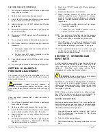
SECTION 18. DERATING FOR HIGH
ALTITUDE
At higher altitudes, the density of the air is reduced.
Therefore, for proper combustion, the quantity of gas
burned in the furnace must also be reduced. This is called
derating. Furnaces must be derated when installed at
altitudes greater than 2,000 feet above sea level.
Derating the furnace by adjusting the manifold pressure
lower than the range specified in the Section 16, "Manifold
Pressure Adjustment" is considered to be an improper
procedure.
At elevations above 2,000 feet, the furnace must be
derated 4% for each 1,000 feet above sea level. It is the
installer’s responsibility to see that the furnace input rate is
adjusted properly. Derating must be achieved by reducing
the size of the main burner orifices. Choose the proper
orifices for your altitude and gas heating value from orifice
size Table 8 or 9. In Canada, high-altitude models may be
available which are rated for 2,000 to 4,500 feet above sea
level.
SECTION 19. DETERMINING
CORRECT ORIFICE SIZE
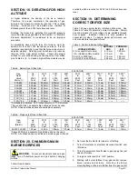
Table 7 shows original factory installed orifice sizes. See
Table 8 or Table 9 to determine correct orifice size. Natural
gas and propane (LP) gas orifice kits are available through
your supplier. Individual orifices are also available in
convenient lot sizes. To assure proper performance, use
only manufacturer supplied orifices.
Table 7. Factory Installed Orifice Sizes.
FURNACE MODEL
NATURAL
GAS
PROPANE
(LP)
U.S. (except NOx models)
2.15 mm
1.30 mm
U.S. (California NOx models)
2.10 mm
NA
CAN. (0 to 2000 feet)
2.15 mm
1.30 mm
CAN. (2001 to 4500 feet)
2.05 mm
1.20 mm
Table 8. Natural Gas Orifice Size.
ELEVATION
Gas
Up
2001 3001 4001 5001 6001** 7001** 8001** 9001**
Heat* to to to to to to to to to
Value
2000 4000 4000 5000 6000 7000 8000 9000 10000
Btu/cu. ft.
Feet
Feet
Feet Feet Feet Feet Feet Feet Feet
800-849
2.35mm
2.30mm
2.30mm
2.25mm 2.20mm 2.20mm 2.15mm 2.10mm 2.05mm
850-899
2.30mm
2.25mm 2.20mm 2.20mm 2.15mm 2.10mm 2.10mm 2.05mm 2.00mm
900-949
2.25mm 2.20mm 2.15mm 2.15mm 2.10mm 2.05mm 2.05mm 2.00mm
1.95mm
950-999
2.20mm 2.15mm 2.10mm 2.05mm 2.05mm 2.00mm
1.95mm
1.95mm
1.90mm
1000-1049
2.15mm 2.10mm 2.05mm 2.05mm 2.00mm
2.00mm
1.95mm
1.90mm
1.85mm
1050-1099 2.10mm
2.05mm
2.00mm
2.00mm
1.95mm
1.90mm
1.90mm
1.85mm
1.85mm
1100-1149 2.05mm
2.00mm
2.00mm
1.95mm
1.95mm
1.90mm
1.85mm
1.85mm ------
1150-1199
2.00mm
1.95mm
1.95mm
1.90mm
1.90mm
1.85mm ------ ------ ------
*At standard conditions: 30.0 inches Mercury, 60°F, Saturated.
**Above 6000 feet, a separate high altitude kit must be used.
NOTE: Shaded orifices above are available separately.
Table 9. Propane (LP) Gas Orifice Size.
ELEVATION
Gas
Up 2001 3001 4001 5001 6001* 7001* 8001* 9001*
Input to to to to to to to to to
(Btu/Hr) 2000 3000 4000 5000 6000 7000 8000 9000 10000
Feet Feet Feet Feet Feet Feet Feet Feet Feet
40,000-140,000 1.30mm 1.25mm 1.25mm 1.20mm 1.20mm 1.20mm 1.15mm 1.15mm 1.10mm
*Above 6000 feet, a separate high altitude kit must be used.
NOTE: All orifices above are included in propane gas orifice kit.
SECTION 20. CHANGING MAIN
BURNER ORIFICES
WARNING
: To prevent electrical shock and gas
leaks, turn off electrical power and gas before changing
orifices.
Follow this procedure:
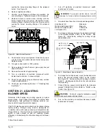
1. Set room thermostat to its lowest or off setting.
2. Turn off electricity at electrical disconnect switch next
to furnace.
3. Turn off equipment shut-off valve in gas supply line just
ahead of furnace.
4. Turn gas control switch to “OFF” position.
5. Starting with burner farthest from gas control, remove
burner screws and burners. Note how the burner
mounting flange of burners farther from the gas control

