Page 6
Installer’s Information Manual
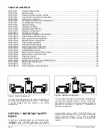
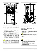
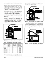
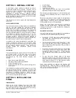
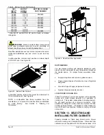
Figure 4. Upflow Configuration.
12. Line up front duct flange with holes in casing. Place
base panel over front duct flange and secure both to
casing with four screws.
13. Install junction box on base panel using two #6B blunt-
point screws removed in step 1. Junction box cover
and screw must face front of furnace.
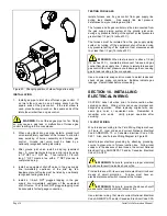
14. Gasket around vent collar must be in place. If gasket
is loose, glue it. If gasket is damaged, replace it.
15. Install a 30-inch or longer section of single wall vent
pipe to the vent collar with three equally spaced
screws. This pipe serves as a vent collar extension to
which an appropriate vent system can be attached.
Additional vent pipe sections or Type B adapter may
then be added when installing the furnace.
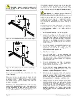
WARNING
: If vent collar extension is shorter than
30 inches and the vent becomes blocked, combustion
products may be drawn into furnace causing the furnace to
produce carbon monoxide. This could cause nausea or
death by asphyxiation.
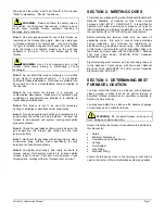
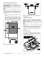
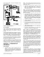
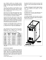
Figure 5. Downflow Configuration.
SECTION 5. ALLOWING FOR
CLEARANCES
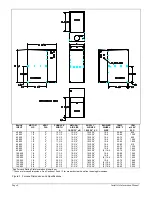
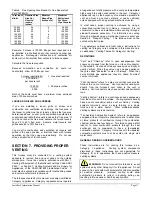
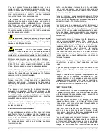
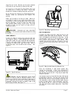
Use tables 1 and 2 for minimum clearances to
combustibles. Also, instructions for attic, crawl space and
suspended furnaces are given.
WARNING
: Furnace installation must meet all
minimum clearances from combustible material specified in
this manual and all applicable codes. Failure to do so could
cause a fire.
WARNING
: Do not install furnace in any of the
following conditions:
*
On carpeting, tile or other combustible material,
except wood flooring
*
In a closet in horizontal position
*
In a downflow position, on wood flooring without
a combustible floor base
Doing any of the above could cause a fire.


