background image

Installation & 

Operation Manual

Rev. 9/2021

Willoughby Industries, Inc.

5105 West 78th Street

Indianapolis, IN 46268

Toll Free:  

(800) 428-4065

Local:    

(317) 875-0830

Fax:    

(317) 875-0837

www.willoughby-ind.com

MADE IN THE 

U.S.A.

Table of Contents

Pre-Installation Information �������������������������������������3

Physical / Rough-in Dimensions �����������������������������4

Required Installation Supplies ��������������������������������5

Parts List ����������������������������������������������������������������6

Exploded-view Drawing ������������������������������������������7

Hardware Identification

 ������������������������������������������8

Installation Instructions ���������������������������������������������

Step 1:  Pedestal Mounting ���������������������������������9

Step 2:  Head and Basin Assembly ������������������10

Step 3:  Drain Assembly ����������������������������������� 11

Step 4A:  Connections for Infrared/Piezo  


                Actuators �������������������������������������������12

Step 4B:  Connections for Pneumatic Actuators

 ��������������������������������������������������������������������������13

Step 5:  Final Assembly ������������������������������������14

JACO Fitting Instruction ����������������������������������������15

Adjustable Mixing Valve Installation ���������������������16

Infrared Sensor Installation Instructions ���������������17

Pneumatic Valve Operation Details ����������������������18

Liquid Soap Specification and Maintenance

 ���������19

Care and Maintenance �����������������������������������������20

Troubleshooting ��������������������������������������������������������

Infrared Sensors �����������������������������������������������21

Electronic Valves ����������������������������������������������22

Pneumatic Valves ���������������������������������������������23

Drawings �������������������������������������������������������������������

General Dimensions and Rough-in Detail ��������25

Valve Details �����������������������������������������������������26

Miscellaneous Details ���������������������������������������32

Warranty ���������������������������������������������������������������36

WAF-3606 Series

AquaFount

®

 36" 360° 

Solid Surface Washfountain

Electronic/Pneumatic

WAF-3606

Summary of Contents for AquaFount WAF-3606 Series

Page 1: ...asin Assembly 10 Step 3 Drain Assembly 11 Step 4A Connections for Infrared Piezo Actuators 12 Step 4B Connections for Pneumatic Actuators 13 Step 5 Final Assembly 14 JACO Fitting Instruction 15 Adjust...

Page 2: ...tallation Operation Manual AquaFount 360 Washfountain WAF 3606 Series Willoughby Industries Inc TOLL FREE 800 428 4065 LOCAL 317 875 0830 FAX 317 875 0837 Page 2 www willoughby ind com Page intentiona...

Page 3: ...ww willoughby ind com 2210 West Morris Street P O Box 21217 Indianapolis IN 46221 317 638 2381 Fax 317 638 6110 800 428 4065 Rev 11 2007 Page 3 Installation notice Check Rough in location and flush li...

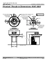
Page 4: ...ation Operation Manual AquaFount 360 Washfountain WAF 3606 Series Willoughby Industries Inc TOLL FREE 800 428 4065 LOCAL 317 875 0830 FAX 317 875 0837 Page 4 www willoughby ind com Physical Rough in D...

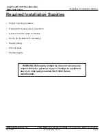
Page 5: ...hby ind com Required Installation Supplies Proper mounting hardware Hardware for waste oulet connections Gasket for waste outlet connection Shims for installation if necessary Supply piping Silicone c...

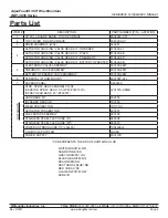
Page 6: ...VE HEAD KIT INFRARED 813600 6I ACTUATOR HOUSING VALVE HEAD KIT PIEZO 813600 6E ACTUATOR HOUSING VALVE HEAD KIT PNEUMATIC 813600 6P ACTUATOR HOUSING VALVE HEAD KIT BATTERY OPERATED 813600 6B 5 ELECTRON...

Page 7: ...Installation Operation Manual AquaFount 360 Washfountain WAF 3606 Series Willoughby Industries Inc TOLL FREE 800 428 4065 LOCAL 317 875 0830 FAX 317 875 0837 Page 7 www willoughby ind com Exploded vi...

Page 8: ...65 LOCAL 317 875 0830 FAX 317 875 0837 Page 8 www willoughby ind com INSTALLATION INSTRUCTIONS Visit our website at http www willoughby ind com 2210 West Morris Street P O Box 21217 Indianapolis IN 46...

Page 9: ...for floor anchoring by others 1 Unpack pedestal and inspect parts 2 Place pedestal at the desired poistion and mark anchor holes anchors by others Make sure that the intended anchor locations will pr...

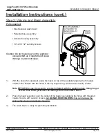
Page 10: ...sonal injury 1 With the help of an assistant place the basin on top of the pedestal aligning the threaded inserts in the bottom with the holes in the top support ring Secure with security screws Note...

Page 11: ...f plumbers putty on the underside of the drain basket lip putty supplied by others 2 Insert the drain basket down through the basin drain hole 3 Secure the drain basket in place by fitting the rubber...

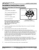
Page 12: ...ed Valve Assembly Plug In Transformer Terminal Block Plate 4 x 3 8 multi colored water lines 20 x security screws 20 tinnerman nuts Wire ties Wire tie mounts adhesive backed 1 Locate terminal block pl...

Page 13: ...ush Button Similar 8 station head kit shown Installation Instructions cont Step 4B Connections for Pneumatic Actuators Parts supplied Valve Assembly pre installed 3 8 x 4 Multi Colored Water Lines Sma...

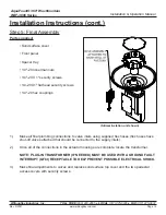
Page 14: ...umbing connections to valve inlets using supplied flex hoses flex hoses have shut off valves attached that should be connected to the supply inlets 2 Once all of the connections in the actuator housin...

Page 15: ...1 Cut tubing end squarely and remove the internal burrs 2 Insert the tubing through the back of the nut all the way through the nut assembly to the tube stop in the fitting body see illustration If t...

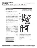
Page 16: ...at outlet If water is not at desired temperature adjust as necessary Speci cations Q e480 00 1 2 NPT Rough Bronze e480 01 1 2 NPT Rough Chrome e480 10 3 8 Compression Rough Bronze e480 11 3 8 Compres...

Page 17: ...off when the user is no longer detected The sensor is set to activate the solenoid for a maximum of 30 seconds before automatically shutting off INSTALLATION AND REPLACEMENT 1 Disconnect 24Vac power...

Page 18: ...lation Operation Manual AquaFount 360 Washfountain WAF 3606 Series Willoughby Industries Inc TOLL FREE 800 428 4065 LOCAL 317 875 0830 FAX 317 875 0837 Page 18 www willoughby ind com Pneumatic Valve O...

Page 19: ...ted with water The pH acidity level should be in the range of 6 5 to 8 5 Soap which is too acidic pH less than 6 5 can corrode stainless steel and degrade rubber plastic or chrome plated materials Soa...

Page 20: ...surf surfaces to strong chemicals such as acetone s paint removers and sulfuric acid or hydrochloric chemical cleaners Exposure to strong chemicals may result in perma nent damage to Aquasurf surfaces...

Page 21: ...solenoid connections C Solenoid problem replace solenoid III No water when activated valve clicks A Make certain that water is turned on B Valve clogged Clean or replace filter IV Very low flow or slo...

Page 22: ...er and the 110V GFCI outlet C If the valve is wired correctly the solenoid will make a click sound indicating that the valve has been actuated The electronic valve is actuated by either the piezo push...

Page 23: ...ct the water diaphragm assembly to see if bypass hole in diaphragm is blocked Remove any debris by blowing on diaphragm or using force of air Do not use any tool such as straight pin to remove any deb...

Page 24: ...allation Operation Manual AquaFount 360 Washfountain WAF 3606 Series Willoughby Industries Inc TOLL FREE 800 428 4065 LOCAL 317 875 0830 FAX 317 875 0837 Page 24 www willoughby ind com Page intentiona...

Page 25: ...ed dimensions are 1 4 Title or Part Description Material Drawn By Date Revision Drawing Approved By N A 1 MODEL WAF 3606 6 STATION JBU 01 29 02 B 810922 Job Name Job Number N A N A Scale NONE Qty Shee...

Page 26: ...llation Operation Manual AquaFount 360 Washfountain WAF 3606 Series Willoughby Industries Inc TOLL FREE 800 428 4065 LOCAL 317 875 0830 FAX 317 875 0837 Page 26 www willoughby ind com DRAWING Electron...

Page 27: ...LCS 0 03 0 015 1 32 1 SIZE PARTS LISTED IN THE PVK REPAIR KITS ARE NOT SOLD INDIVIDUALLY NOTE REPAIR KIT ORDERING S ARE LISTED IN THE EXPLODED VIEW NOTE ITEM PART DESCRIPTION QTY 1 980420 SINGLE TEMP...

Page 28: ...2817 67 7 21 31 80 7 6 7 5 9 25 5 9 6 21 6 5 0 7 3 6 1 6 7 7 6 5 7 216 3 6 37 6 72 5 1 6 127 LOORXJKE QGXVWULHV QF 67 1 5 127 3 57 26 127 6 2 1 7 0 3 57 6 5 37 21 47 02817 1 3 7 30 9 9 6723 66 0 5 31...

Page 29: ...1 8 980135 SPRING AIR SIDE MAGNET 1 9 980405 METERING VALVE MAGNET CUP ASSEMBLY 1 10 980130 DIAPHRAGM AIR SIDE PNEUMATIC METERING VALVE 1 11 980134 AIR SIDE SPRING 1 12 380801M AIR SIDE TOP COVER 1 13...

Page 30: ...EXCEPT AS 0 03 0 015 1 32 Willoughby Industries Inc 803105 8PW ITEM PART DESCRIPTION QTY 1 9805023 MOUNTING PLATE PML23 VALVE 1 2 980183 CHECKSTOP ASSEMBLY 1 3 980416 VALVE ASSEMBLY BATTERY OPERATED 5...

Page 31: ...DAPTOR ASSY 1 3 980114 COIL ADAPTER E1L VALVE 1 4 980170A 8 32 x 1 2 SCREW W SEMS SPLIT L W 4 5 980164 O RING 015 1 6 700255 COIL ASSEMBLY 9VDC LATCHING BATTERY OPERATED 1 7 980680 WASHER NYLON 0 75 I...

Page 32: ...Operation Manual AquaFount 360 Washfountain WAF 3606 Series Willoughby Industries Inc TOLL FREE 800 428 4065 LOCAL 317 875 0830 FAX 317 875 0837 Page 32 www willoughby ind com PIEZO HEAD KIT DETAIL DR...

Page 33: ...PUSH BUTTON DIAPHRAGM PUMP MOLDED 1 4 600201 DIAPHRAGM PNEUMATIC PUMP 1 5 380504MA CAP DIAPHRAGM PUMP MOLDED 1 6 600057 PUSHBUTTON DIAPHRAGM PUMP 1 7 380124 SLEEVE DIAPHRAGM PUMP PUSHBUTTON 1 NOTE PA...

Page 34: ...ead Detail ITEM PART DESCRIPTION QTY 1 800001 WASHFOUNTAIN SPRAYHEAD BASE 45 S S 1 2 320157A SPRAY HEAD 0 5 GPM 13 16 27 THREAD 1 A BEH BEH 08 05 14 08 05 14 A 1 OF 1 STANDARD 320157A ASMB 3 2 PART SP...

Page 35: ...1 21 127 5 8 7 217 16 7 2 2 1 7 0 3 57 6 5 37 21 47 2 5 1 62 3 3803 6 1 58 5 33 5 9 9 62 3 3803 62 3 3803 635 1 6 7 62 3 3803 3 6721 635 1 2 5 1 3 6721 62 3 3803 3 6721 1 803 5 62 3 3803 9 9 6 5 6 7...

Page 36: ...installation or any other labor charges and does not apply to any components damaged by accident abuse improper installation or improper maintenance This warranty does not cover any installation that...

Reviews: