WILLOUGHBY
INDUSTRIES
ACCESSORY FAUCET ASSEMBLY
INSTALLATION & OPERATION MANUAL
1.800.428.4065
TOLL FREE
| www.willoughby-ind.com
PAGE
2
© Rev.
2/2021
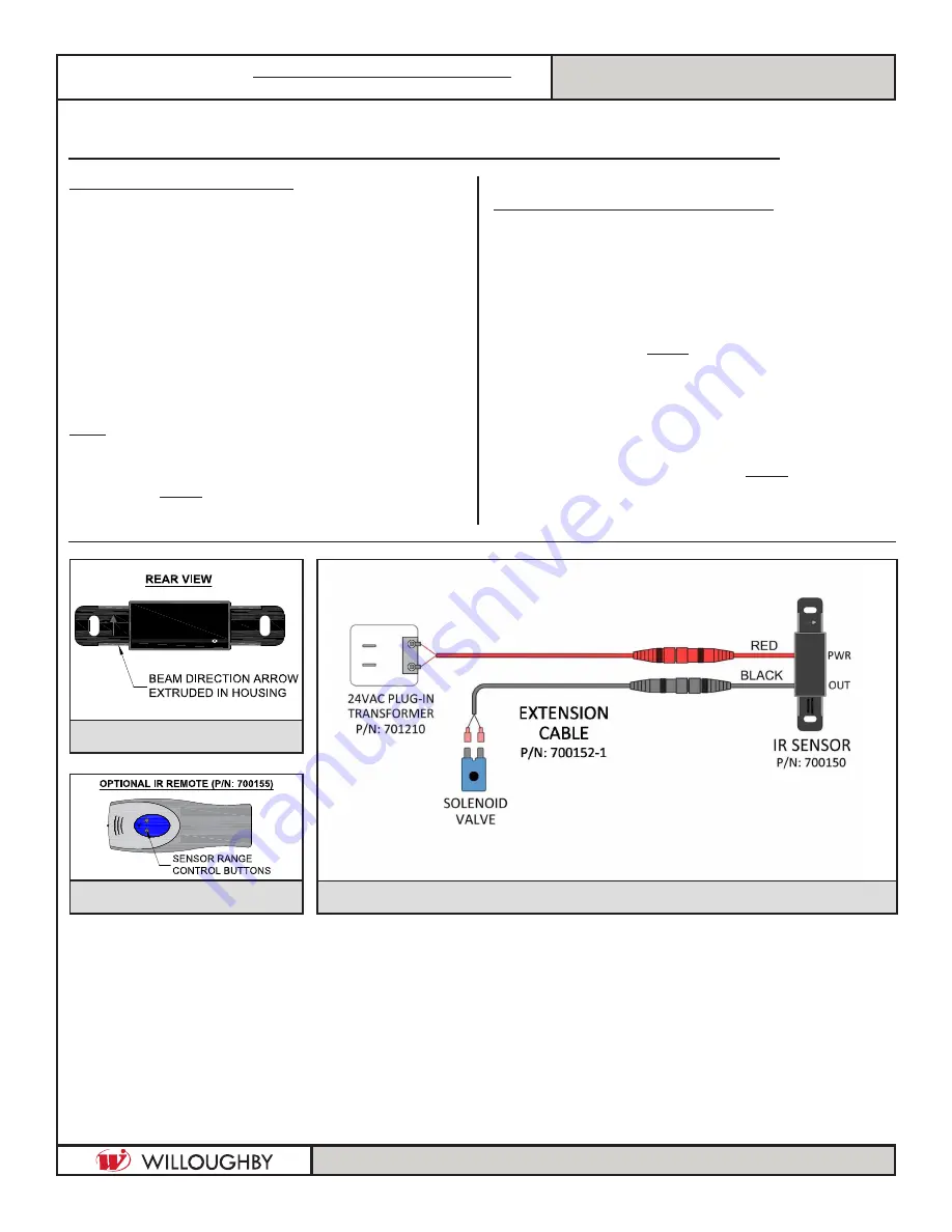
FIG. 3-
24V AC SYSTEM INFRARED ASSEMBLY
FIG. 1-
IR SENSOR
FIG. 2-
IR REMOTE
DETECTION AND ACTIVATION
- When the sensor detects a user, a slow-flashing
red light appears in the sensor window.
- After 1-2 seconds of detection, the light flashes
rapidly, the sensor immediately activates the
solenoid valve, beginning water flow.
- The valve remains open while the user is detected.
- The valve closes when the user is no longer detected.
- The sensor is set to activate the solenoid valve for a
maximum of 30 seconds before automatically
shutting off.
Note:
Sensor range is factory preset to 20";
Optional range adjustment remote available
to adjust range from 1" min. to 30" max.
(SEE FIG. 2)
.
INSTALLATION AND REPLACEMENT
1) Disconnect the 24V AC power at either the
transformer or fuse box.
2) Remove the faucet to expose the sensor and sensor
mounting bracket.
3) Remove the PTC fitting and sensor mounting bracket.
4) Install the new sensor with arrow pointing
upwards
(SEE FIG. 1).
4) Replace the sensor mounting bracket and PTC fitting.
5) Remount the faucet to the fixture making sure both the
red and black cables from the sensor are pushed
through the center hole.
6) Connect the red male power cable to the female
connector on the sensor
(SEE FIG. 3).
7) Connect the black female solenoid cable to the
male connector on the sensor
.
8) Reconnect the power.
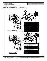
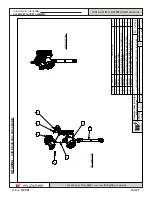
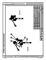
(LRFC) FAUCET
24V AC System Infrared Sensor


