background image

2

Contents

Page

1) General

3

2) Safety Instructions

2.1 Symbols and Signals

3

2.2 Modification and Spares

3

3) Transport and Storage

3

4) Description and Operation

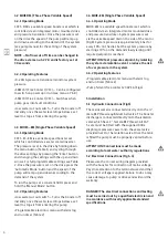
4.1 MHI PS-EM (Single Phase Fixed Speed)

3

4.1.1 Operation Modes

3

4.1.2 Operating Features

3

4.2 MHIE DM (Three Phase Variable Speed)

4

4.2.1 Operation Modes

4

4.2.2 Operating Features

4

4.3  MHI EC-EM (Single Phase Variable Speed)

4

4.3.1 Operation Modes

4

4.3.2 Operating Features

4

4.4  MHIE EM (Single Phase Variable Speed)

4

4.4.1 Operation Modes

4

4.4.2 Operating Features

4

5) Installation

5.1 Hydraulic Connections

4

5.2 Electrical Connections

4

6) Commissioning

6.1 Commissioning

5

6.2 Maintenance

5

7) Warranty

5

8) Figures

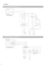
Fig 1 MHI PS-EM Electrical Connections

6

Fig 2 MHIE DM Electrical Connections

6

Fig 3 MHI EC-EM Electrical Connections

7

FIg 4 MHIE EM Electrical Connections

7

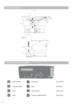
Fig 5 System General Arrangement

8

Fig 6 MHI PS-EM General Arangement

8

Fig 7 MHIE DM General Arrangement

9

Fig 8 MHIE EM Controls

9

Fig 9 MHI EC-EM General Arrangement

10

9) Tables

Table 1 EC-EM Drive User Interface

10

Table 2 EC-EM Settings Menu

11

Table 3 Drive Fault Codes

12

10) Spares

Spares 1 PS-EM & DM

13

Spares 2 EC-EM-2

14

11) Certificate of Conformity

15

Summary of Contents for 2819142

Page 1: ...819146 CAT5 1MHI206 PS EM 29992804 CAT5 1MHI206 EC EM 2 2819147 CAT5 1MHI402 PS EM 29992805 CAT5 1MHI402 EC EM 2 2819148 CAT5 1MHI403 PS EM 29992806 CAT5 1MHI403 EC EM 2 2819149 CAT5 1MHI404 PS EM 299...

Page 2: ...s 4 4 4 2 Operating Features 4 5 Installation 5 1 Hydraulic Connections 4 5 2 Electrical Connections 4 6 Commissioning 6 1 Commissioning 5 6 2 Maintenance 5 7 Warranty 5 8 Figures Fig 1 MHI PS EM Elec...

Page 3: ...ifficulty is mentioned 2 2 Modification and Spare Parts Modifications to the booster are prohibited and will invalidate the warranty Wilo Approved spares must be used at all times For information on s...

Page 4: ...set level to stop air from entering the pump Programmable electronic menu with alarm log and run timer Table 2 4 4 MHIE EM Single Phase Variable Speed 4 4 1 Operating Mode MHIE EM is a variable speed...

Page 5: ...recommend that the expansion vessel is checked at least annually This may require more frequent checks if the unit is subject to higher frequencies of use Checks should be made on condition of stored...

Page 6: ...6 Fig 1 MHI PS EM Electrical Connections Fig 2 MHIE DM Electrical Connections 8 Figures...

Page 7: ...7 Fig 3 MHI EC EM Fig 4 MHIE EM Electrical Connections...

Page 8: ...8 Fig 5 General Arrangement Hydraulic Fig 6 PS EM Layout...

Page 9: ...9 Fig 7 MHIE EM DM Layout Fig 8 MHIE EM Controls...

Page 10: ...10 Manual Mode Inverter On Green LED Automatic Mode Alarm Red LED Menu Pump Running Yellow LED Enter Pump in Automatic Mode Green LED Table 1 Driver User Interface EC EM Fig 9 MHI EC EM Layout...

Page 11: ...ressure before the pumps start 0 3 Bar Time Before Stop Time the pumps will run once the pressure has been reached at no flow 15 Sec MENU HISTORIC Running Time Total pump running hours Hrs Pump Cycles...

Page 12: ...technical service depart ment E031 OVER T If the temperature is too high the controller will stop the motor from running Check that the water temperature does not exceed 40 C Check that the ambient te...

Page 13: ...1 230 4024288 MHi205 1 E 1 230 4024290 MHi206 1 E 1 230 4024292 MHi402 1 E 1 230 4024294 MHi403 1 E 1 230 4024296 MHi404 1 E 1 230 4024298 MHi405 1 E 1 230 4024300 MHi406 1 E 1 230 4148406 MHIE205N 1...

Page 14: ...2 Pumps 4024283 MHi202 1 E 3 4024285 MHi203 1 E 3 4024287 MHi204 1 E 3 4210718 MHi205 1 E 3 4210722 MHi206 1 E 3 4024293 MHi402 1 E 3 4024295 MHi403 1 E 3 4210725 MHi404 1 E 3 4210732 MHi405 1 E 3 421...

Page 15: ...Electromagnetic Compatibility Directive WEEE Directive ROHS Directive As well as following harmonized standards If the above mentioned series are technically modified without our approval this declar...

Page 16: ......

Reviews: