4
4.2 MHIE DM (Three Phase Variable Speed)
4.2.1 Operating Mode
CAT 5 DM is a variable speed booster set which is
controlled via an integrated motor mounted drive
and pressure transducer. Once the pressure is set
on the drive the speed of the pump will ramp up
and down according to the demand of the system
(see pump manual for the setting of the system
pressure)
NOTE – No flow cut off time can be changed in
the drive via menu 5.2.7.0 and is factory set at
30 seconds
4.2.2 Operating Features
•0-20mA pressure transducer monitors system
pressure
•SBM Volt Free Contact (VFC) – Can be configured
to switch on power up or run (see menu 4.7.6.0)
•SSM Volt Free Contact (VFC) – Switches when
pump goes into fault conditions
•Low water cut out switch – Turns the booster off
instantly once the water level drops below a set
level to stop air from entering the pump
4.3 MHI EC-EM (Single Phase Variable Speed)
4.3.1 Operating Mode
CAT 5 EC-EM is a variable speed booster set
which is controlled via a water cooled inverter.
The pressure is set in the drive by holding down
the menu button (Table 1) and cycling through
the drive settings by pressing the ‘Enter’ button
and changing the settings with the up and down
arrows. For full programmable settings see Table
2. Once the pressure is set on the drive press the
‘Automatic Mode’ button and the speed of the
pump will ramp up and down according to the
demand of the system.
To run the pumps at a constant 50Hz press and
hold the ‘Manual Mode’ button
4.3.2 Operating Features
•Low water cut out switch – Turns the booster off
instantly once the water level drops below a set
level to stop air from entering the pump
•Programmable electronic menu with alarm log
and run timer (Table 2)
4.4 MHIE-EM (Single Phase Variable Speed)
4.4.1 Operating Mode
MHIE-EM is a variable speed booster set which is
controlled via an integrated motor mounted drive
and pressure transducer. System pressure is set
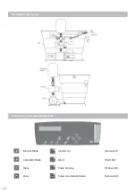
via the variable speed dial on the side of the motor
(Fig8). System pressure is approximately 1 bar for
every 10% on the dial. Set the system pressure by
starting at 0% on the dial and slowly raising until
required setpoint is reached.
ATTENTION! Test pressure setpoint, by isolating
the system via isolation valve to reduce the risk
of over pressure in the system
4.4.2 Operating Features
•Programmable electronic menu with alarm log
and run timer (Table 2)
•Pump fail volt free contact 230V 1A (Fig4)
5 Installation
5.1 Hydraulic Connections (Fig5)
The mains water is connected directly onto the ½”
male BSP thread equilibrium ball valve. The booster
discharge is connected directly onto the isolation
valve which has a 1” female BSP thread. All CAT
5 sets must be fitted with the supplied 8 litre
diaphragm pressure vessel onto the vessel valve
provided next to the isolation valve. Once the tank
is filled the pump must be properly vented before
use.
ATTENTION! Connections must be made
according to local water authority regulations
5.2 Electrical Connections (Fig1-4)
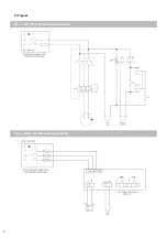
Please use the correct wiring diagram provided
with the booster for connection of mains voltage.
Pay close attention to the terminals used and that
the correct voltage is applied. Failure to do so may
cause damage to pump or drives and will void the
warranty.
DANGER! The electrical connections and testing
must be carried out by a qualified electrician and
in accordance with locally applicable standard
specifications.
Summary of Contents for 2819142
Page 6: ...6 Fig 1 MHI PS EM Electrical Connections Fig 2 MHIE DM Electrical Connections 8 Figures...
Page 7: ...7 Fig 3 MHI EC EM Fig 4 MHIE EM Electrical Connections...
Page 8: ...8 Fig 5 General Arrangement Hydraulic Fig 6 PS EM Layout...
Page 9: ...9 Fig 7 MHIE EM DM Layout Fig 8 MHIE EM Controls...
Page 16: ......


