English
50
WILO SE 08/2016
DANGER! Risk of fatal injury!
The tools used during maintenance work on the motor shaft can be
flung out if they come into contact with rotating parts, and cause
serious or even fatal injuries.
• The tools used during maintenance work must be removed
completely before the pump is started up.
9.1
Air supply
The air supply to the motor housing must be checked at regular inter-
vals. In case of contamination, ensure that an air supply is re-estab-
lished in order to allow the motor to cool sufficiently.
9.2
Maintenance tasks
DANGER! Danger of death!
Falling pumps or pump parts may result in life-threatening injuries.
• When performing installation work, protect the pump components
against falling.
DANGER! Risk of fatal injury!
There is a risk of fatal injury from electric shock when working on
electrical equipment.
• Check for absence of voltage and cover or cordon off adjacent live
parts.
9.2.1
On-going maintenance
Replace all gaskets that have been removed for maintenance.
9.2.2
Replacing the mechanical seal
The mechanical seal is maintenance-free. There may be a slight
amount of drip leakage during the running-in period. Even during
normal operation of the pump, slight leakage involving occasional
drops is common. Once in a while, however, a visual inspection is
required. If there is clearly detectable leakage, the gasket is to be
changed.
Wilo offers a repair kit which contains the necessary parts for
replacement.
Dismantling
Dismantling:
• Disconnect the system from the power and secure it against being
switched on.
• Make sure it is not live.
• Earth the work area and short-circuit.
• Close the shut-off device upstream and downstream of the pump.
• Disconnect the mains connection cable.
• Depressurise the pump by opening the venting screw
DANGER! Risk of scalding!
Due to high fluid temperatures there is a danger of scalding.
• At high fluid temperatures, let the pump cool down before starting
any work.
NOTE:
• When tightening screw connections in conjunction with the work
described in the following: Observe the screw tightening torque for
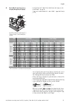
the thread type (see list "Table 5: Screw tightening torques" on
page 54).
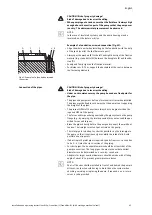
• Dismantle the coupling guard metal sheets (Fig. 1, item 1).
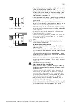
• Rotate the coupling/shaft in such a way that the four hexagon socket
screws (twist guard; Fig. 2, item 1) are opposite to the cover/drilled
holes.
• Unscrew the hexagon socket screws (locking pins) one after the other
far enough that the head is countersunk half way in the cover collar
(Fig. 2 or Fig. 3, depending on the pump type).
Summary of Contents for CronoBloc BL Series
Page 3: ...Fig 7 Fig 8 2 1 3 Fig 9 Fig 10 3 2 1 Fig 11 ...
Page 5: ...Fig 18 Fig 19 1 2 1 Fig 20 Fig 21 Fig 22 Fig 23 1 1 2 ...
Page 37: ......
Page 38: ......
Page 39: ......


