English
Installation and operating instructions Wilo-VeroLine-IPS
25
• Always use suitable lifting equipment and secure parts against fall-
ing.
• When performing installation and maintenance work, protect the
pump components against falling.
• Never stand underneath a suspended load.
CAUTION! Risk of material damage!
Danger of damage due to incorrect handling.
• Have the pump installed by qualified personnel only.
CAUTION! Damage to the pump due to overheating!
The pump must not be allowed to operate dry for more than
1 minute. Dry running causes a build-up of energy in the pump,
which can damage the shaft, impeller, and mechanical seal.
• A minimum flow of approximately 10% of the maximum flow rate
must be ensured at all times.
7.1
Installation
Preparation
• The pump should only be installed after completion of all welding and
soldering work and, if necessary, flushing of the pipe system. Dirt can
cause the pump to fail.
• Standard pumps must be protected from the weather and installed in
a frost/dust-free, well-ventilated environment which is not poten-
tially explosive.
• Install the pump in a place that is easy to access so that subsequent
inspections, maintenance (e.g. mechanical seal) or replacement is
easily possible.
Positioning/alignment
• Minimum distance between a wall and the fan guard of the motor:
30 cm.
• The direction of flow must correspond to the direction arrow on the
housing.
• Shut-off devices must be installed without fail in front of and behind
the pump in order to avoid the entire system being drained when the
pump is inspected or exchanged.
If there is a danger of return flow, a non-return valve must be used.
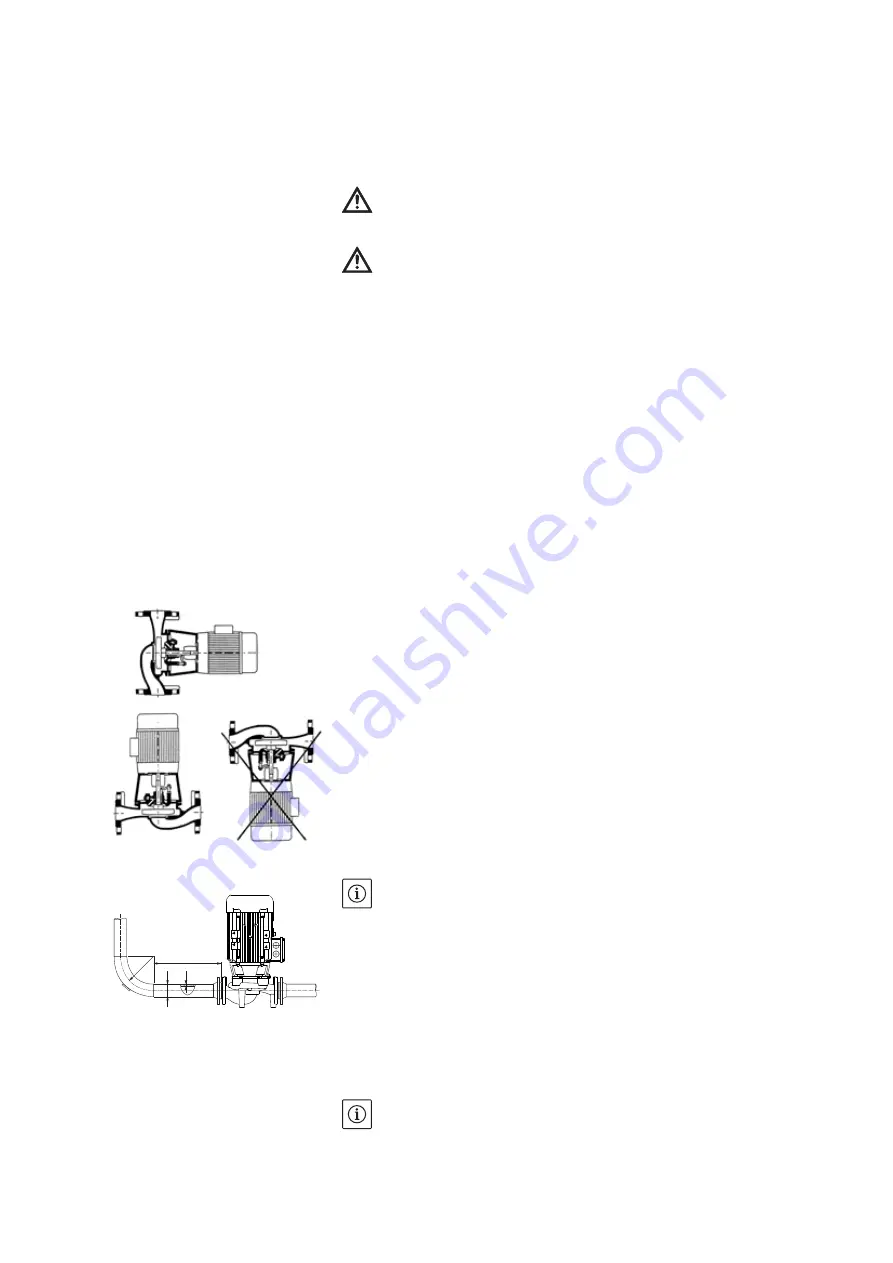
• All installation positions except for "motor facing down" are allowed
NOTE
A settling section must be provided before and after the pump, in the
form of a straight pipe. The length of this settling section should be at
least 5 x DN of the pump flange (Fig. 3). This measure serves to avoid
flow cavitation.
• There is an indent in the lantern area to collect condensate or small
quantities of liquid. This liquid can be drained off via a hole in the lan-
tern.
The lantern has an opening on the underside which allows a drain pipe
for condensation water to be connected.
• The pipes and pump must be free of mechanical stress when installed.
• The air vent valve must always point upwards.
NOTE
The pump must always be mounted so that the motor terminal box
points upwards and the drain hole in the lantern points downwards.
This achieves the following:
Fig. 2: Permitted installation positions
Fig. 3: Settling section before and after the
pump
r
5 x DN
d
s
r
⬇
2,5 · (d · 2s)
Summary of Contents for VeroLine-IPS 20
Page 2: ......
Page 3: ...Fig 1 ...
Page 4: ......
Page 5: ...de Einbau und Betriebsanleitung 3 en Installation and operating instructions 19 ...
Page 38: ......


