English
Installation and operating instructions Wilo-VeroLine-IPS
27
• Check the current type and voltage of the mains connection.
• Observe the rating plate information for the pump. The current type
and voltage of the mains connection must correspond to the details
on the rating plate.
• Fuse on mains side: 10 A, slow-blow.
• Earth the pump/installation in accordance with the regulations.
NOTE
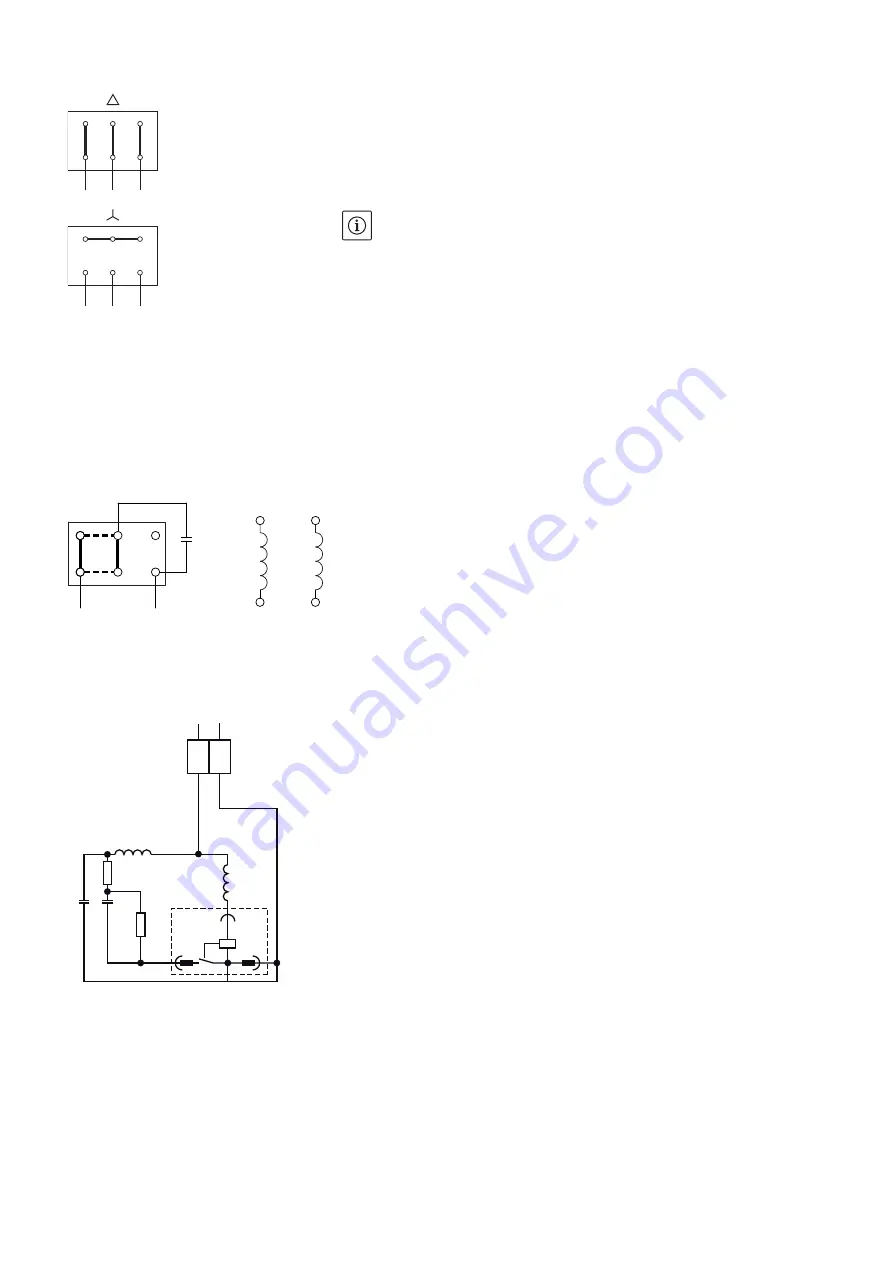
The connection diagram for the electrical connection can be found in
the terminal box cover (see also Fig. 4 - 6).
• For connection voltage see motor rating plate.
• When connecting automatic switchgears/frequency converters,
observe the corresponding installation and operating instructions.
The following are to be observed in addition to other aspects:
• Appropriate cable with sufficient cross-section (max. 5% voltage
loss).
• Connect correct shielding according to the recommendation of the
frequency converter manufacturer.
• Install data cables (e.g. PTC analysis) separately from the mains
cable.
• Possible utilisation of a sine filter (LC) upon consultation with the
frequency converter manufacturer.
Installation/setting of the motor
protection switch
• The use of a motor protection switch is necessary.
• Set according to the nominal motor current specified on the rating
plate of the motor, Y-
Δ
starting: If the motor protection switch is
switched in the supply line to a Y-
Δ
contactor combination, set the
switch as for direct starting. If the motor protection switch is switched
in a thread of the motor supply line (U1/V1/W1 or U2/V2/W2), set the
motor protection switch to 0.58 x rated motor current.
Fig. 4: Mains connection
L1
L2
L3
L1
L2
L3
W2
U2
V2
U1
V1
W1
W2
U2
V2
U1
V1
W1
Fig. 5: Mains connection 1~ with operating capacitor
Fig. 6: Mains connection 1~ with starting and oper-
ating capacitor
Z1
CB
U
1
L
N
Z
2 U2
Z
2
U2
Set bridges horizontally for
reversal of rotation direction.
Z1
BK
R
V
Z
2
L
N
GY
RD
U
1
U2
WH
CA
CB
RE
2
4
3
Summary of Contents for VeroLine-IPS 20
Page 2: ......
Page 3: ...Fig 1 ...
Page 4: ......
Page 5: ...de Einbau und Betriebsanleitung 3 en Installation and operating instructions 19 ...
Page 38: ......


