background image

W I L S O N   A U D I O   S P E C I A L T I E S ,   I N C .

8-5

S

E C T I O N

  8   -   T

I M I N G

 T

A B L E S

F

OR


A

 G

RAPHICAL

 I

LLUSTRATION


OF


THIS

 D

ATA

, S

EE

 N

OMOGRAPH

 O

N


THE

 N

EXT

 P

AGE

Summary of Contents for Alexandria X-2 Series

Page 1: ......

Page 2: ...W I L S O N A U D I O S P E C I A L T I E S I N C ...

Page 3: ...W I L S O N A U D I O S P E C I A L T I E S I N C ...

Page 4: ...change without notice Current Revision 1 0 September 2003 If you are in need of a more recent manual please contact your dealer The information in this manual is the sole property of Wilson Audio Specialties Inc Any reproduction in whole or in part without the express written permission of Wilson Audio Specialties Inc is prohibited No material contained herein may be transmitted in any form or by ...

Page 5: ...EXANDRIA IN A DEDICATED HOME THEATER 1 7 SPEAKER PLACEMENT VS LISTENING POSITION 1 9 SPEAKER ORIENTATION 1 9 SUMMARY 1 10 SECTION 2 0 UNCRATING THE ALEXENDRIA 2 1 INITIAL CHECK 2 1 MATERIALS REQUIRED 2 1 UNCRATING THE WOOFER CABINETS 2 1 UNPACKING THE WOOFER 2 1 UNCRATING THE WING ASSEMBLY 2 2 UNCRATING THE UPPER ARRAY MODULES 2 3 UNCRATING THE CROSSOVER COVER 2 4 SPIKE ASSEMBLY 2 5 CRATE CONTENTS...

Page 6: ...NSTALLATION 3 11 MATERIALS REQUIRED 3 11 INSTALLATION PROCEDURE 3 12 LEVELING THE ALEXANDRIA X 2 3 13 SECTION 3 6 EXPANSION BOLTS 3 14 SECTION 3 7 INSTALLING THE BACK COVER 3 15 SECTION 3 8 RESISTORS 3 16 SECTION 4 0 CARE OF THE ALEXANDRIA X 2 4 1 PAINTED FINISH 4 1 BREAK IN PERIOD 4 2 SECTION 4 1 ENCLOSURE CONSTRUCTION 4 2 MATERIAL 4 2 ADHESIVE 4 2 DEPTH OF DESIGN 4 3 CONCLUSION 4 3 SECTION 5 0 W...

Page 7: ... MODULE 3 1 FIGURE 12 MEASURING EAR HEIGHT AND LISTENING DISTANCE 3 2 FIGURE 13 ALIGNMENT PLATE WITH SPIKE DETENTS 3 3 FIGURE 14 INSERT TETHER BOLTS BEFORE ATTACHING PLATE TO WOOFER 3 5 FIGURE 15 ATTACH PLATE TO LOWER WING 3 5 FIGURE 16 UPPER MODULES 3 6 FIGURE 17 INSTALLING UPPER MODULES 3 7 FIGURE 18 CABLE DRESSING 3 8 FIGURE 19 CONNECTING THE CABLES TO THE UPPER MODULES 3 9 FIGURE 20 INSTALLING...

Page 8: ...W I L S O N A U D I O S P E C I A L T I E S I N C FIGURE 1 ALEXANDRIA DIMENSIONS UPPER ARRAY CROSSOVER iv ...

Page 9: ...W I L S O N A U D I O S P E C I A L T I E S I N C IN T R O D U C T I O N ...

Page 10: ...W I L S O N A U D I O S P E C I A L T I E S I N C ...

Page 11: ...pottedincasesmilledfromsolidbilletsof X material Microphonicsandmechanical interferencearegreatlyreducedthroughthisaggressivestrategy Applyingnewtechnologyintherealm of group delay jitter the X 2 crossover is the most time coherent yet produced The crossovers are located behind a removable rear door providing easy access to resistors and other serviceable items New combinations of M and X material...

Page 12: ... the drivers will also introduce tonal anomalies that destroy the otherwise convincing presence of an instrument or a singer s voice Wilson s solution for group delay correction has long set the standard for precise driver positioning in order to insure correct time alignment for a wide range of real room listening distances and ear heights The signature curves in Alexandria s cabinet are a furthe...

Page 13: ...ibit less than optimum group delay and dispersion characteristics The sound quality is compromised for all listeners in all rooms With Alexandria for the first time ever you and others you listen with will hear your favorite recordings and soundtracks with true time coherency full frequency range unfettered dynamics and vanishingly low distor tion TheimprovementinrealismwroughtbyAlexandria isdelig...

Page 14: ...W I L S O N A U D I O S P E C I A L T I E S I N C ...

Page 15: ...W I L S O N A U D I O S P E C I A L T I E S I N C SE C T I O N 1 0 RO O M AC O U S T I C S ...

Page 16: ...W I L S O N A U D I O S P E C I A L T I E S I N C ...

Page 17: ...inedinsettingupWilsonloudspeakersandwillensurethatyourealizethefullvalue of your purchase ZONE OF NEUTRALITY The Zone of Neutrality is an area in your room where the speakers will sound most natural This loca tion is where the speakers interact the least with adjacent room boundaries It is important to have a clear working spacewhiledeterminingtheZoneof Neutrality Thefollowingisasimplemethodtoloca...

Page 18: ...ed speaker location Stand between the two tape marks Using the same procedure as above begin moving into the room toward the opposite side wall progressing between the two pieces of tape As above listen for the point in the room where your voice transitions from bass heavy and diffuse to neutral Mark this point with tape Continueyourprogressionuntilthereisanobviousinteractionwiththeoppositewallinf...

Page 19: ...is nonparallel walls This is because rather than support slap echo nonparallel walls allow the sound to diffuse This approach can be accounted for during the construction process For existing rooms slap echo can also be controlled entirely by the application of absorptive materials to the hard surfaces These are absorptive materials than can be used to ameliorate slap echo Sonex Airduct board Cork...

Page 20: ...han slap echo because they tend to occur at a lower fre quency Absorbentmaterials suchasSonex areineffectiveatcontrollingreflectionsinthebassregion Moving speakers about slightly in the room is for most people their only control over standing waves Sometimes a change of placement of as little as two or three inches can dramatically alter the tonal balance of a small system Fortu nately minorlowfre...

Page 21: ...rect sound This cancellation is most apparent where the two frequencies are 180 degrees out of phase Further there is augmentation at other frequencies where the direct and the reflected sounds arrive in phase Because it is a function of wavelength the comb filter effect will notch out portions of the audio spectrum at regular octave spacedintervals Subjectively combfiltereffectevidencesitselfasfo...

Page 22: ...ut their contribution to the sound of the speaker is more progres sive Rattlingwindows pictureframes lampshades etc cangenerallybesilencedwithsmallpiecesofcaulkor withblocksoffelt However shortofactuallyaddingadditionallayersofsheetrocktoflimsywalls thereislittlethat can be done to eliminate wall resonances AIR VOLUME RESONANCE The volume of air in a room will also resonate at a frequency determin...

Page 23: ...ular rooms are still preferred to square rooms because by having two sets of dissimilar lengthwalls standingwavesarenotasstronglyreinforcedandwilldissipatemorequicklythaninasquareroom In these rooms the preferred speaker position for spatial placement and midrange resolution would be on the longer walls Bass response would be reinforced by speaker placement on the short walls In many cases L shape...

Page 24: ...W I L S O N A U D I O S P E C I A L T I E S I N C F IGURE 5 P OSSIBLE P LACEMENT WITHIN V ARIIOUS R OOM S HAPES ALEXANDRIA OWNER S MANUAL 1 8 ...

Page 25: ...ce the speakers on one end and sit at the other end of the room This approach will not yieldthefinestsound Carefullyconsideryourlisteningposition Ourexperiencehasshownthatanylistening positionwhichplacesyourheadcloserthan14 fromaroomboundarywilldiminishthesonicresultsofyour listening Decidewhereyouwantyourfavoritelisteningpositiontobe PleaserememberthatyourAlexandrias will fillalmostanyroomwiththe...

Page 26: ...de of each Alexandria Toeing in the speakers provides meaningful improvementsinresolutionoflowleveldetailinthemidrangeaswellasappreciableimprovementsinsoundstaging performance SUMMARY Insummary foroptimaltonalbalanceaccuracy resolutionoflowleveldetail andsoundstagingperfor mance the Alexandria should be positioned as outlined in this section Ideally the speakers should not be posi tionedtoofarfrom...

Page 27: ...W I L S O N A U D I O S P E C I A L T I E S I N C 1 11 ...

Page 28: ......

Page 29: ...SE C T I O N 2 0 UN C R AT I N G T H E AL E X A N D R I A X 2 ...

Page 30: ...W I L S O N A U D I O S P E C I A L T I E S I N C ...

Page 31: ...se check their condition If any of the crates are damaged please report it to the shippingcompanyimmediatelyforinsuranceverification TOOLS REQUIRED Metalshears Variablespeed reversibleelectricdrill Phillipsheaddrivebit UNCRATING THE WOOFER MODULES A minimum of two strong adults is required to set up the system Locate the two largest crates labeled Woofer Modules These contain the woofer enclosures...

Page 32: ...have not yet performed this room analysis please refer to Section 1 0 of this manual Reminder Place the odd serial numbered woofer on the LEFT and the even numbered moduleontheRIGHT 5 Remove the empty woofer crates from the room UNCRATING THE ASPHERICAL WINGS Locate the two crates labeled Wing Array see Figure 7 These contain the wings that support the upper modules Locate the serial plate on the ...

Page 33: ... another by serial number The serial tags are located on the under side of each module and on the underside of the group delay alignment plate B e very careful in unpackingtheremainingmodulestoavoidchippingthefinish 2 Stagetheseitemsawayfromtrafficflow 3 Remove the empty crates from the room SE C T I O N 2 0 UN C R AT I N G T H E AL E X A N D R I A UPPER MIDRANGE MODULE UMRM HIGH FREQUENCY MODULE ...

Page 34: ...OVER 1 Locate the crate labeled Crossover Cover see Figure 9 This crate contains the two rear crossover covers Remove them from the crate Take care to observe the serial number and place the covers withthecorrespondingchannel smodules 2 Remove the empty crates from the room 2 4 FIGURE 9 CROSSOVER COVER ...

Page 35: ...kes You will need to unscrew them when you level the Alexendrias Place the set screw into the other end of the diode with the Allen head toward the spike This will ensure that if for any reason you have to remove your Alexandria spikes you will be able to withdraw the set screw safely using the supplied Allen wrench Screw the set screw into the diode until it meets the spike see Figure 10 Placethe...

Page 36: ...dules left rightchannel 2 Upper mid range modules left right channel 2 Wings left rightchannel 2 GroupDelayAlignmentPlates left rightchannels 8 3 8 16x 1 5 set screws 8 Spikes with nuts 8 Woofer Paws 1 Caster wrench 1 7 16 Ractcheting wrench 1 Jack 1 7 16 Combo wrench 1 9 16 Combo wrench 1 3 16 Long arm Allen wrench 1 5 32 Allen wrench 1 1 2 Binding post wrench 1 9 16 Combo wrench 6 Expansion spik...

Page 37: ...hs 8 Brass spike pads 1 Bottoming tap 3 8 16 1 Tap Handle 24 20 x 1 Button headed capscrew 12 20 x 1 Socket head screws 16 10 32 x 1 Socket head screws 16 10x 438 Washer Complete set of resistors After set up of the system keep the shipping crates in case of future shipping needs SE C T I O N 2 1 CR AT E CO N T E N T S CH E C K L I S T ...

Page 38: ......

Page 39: ...SE C T I O N 3 0 AL E X A N D R I A SY S T E M SE T U P ...

Page 40: ...W I L S O N A U D I O S P E C I A L T I E S I N C ...

Page 41: ...from many years of experience and should be followed closely First place the woofer modules in the zone of neutrality as determined by the procedure outlined in Section 1 0 FinalsetupandtuningwillfollowtheassemblyofyourAlexandrias Remove the protective film covering the painted surfaces on the modules wing assemblies and crossover covers Start at the edge and slowly peel it off Each wing array has...

Page 42: ...this section are a result of this testing ROOM SETUP AsindicatedinFigure12 theAlexandria systemallowsfordifferentlisteningdistances awayfromthe speakers and listening ear heights measured distances from the floor to your ear For each distance ear height combinationthereisauniquealignmentgeometry To make correct in home set up of the Alexandria possible without test equipment Wilson Audio has measu...

Page 43: ...roup delaypositionwithinthemodulararray Eachalignmentplatecontainsnumberedindents numbered1to33 see Figure13 Thealignmenttablescontaintheinformationforpositioningeachmoduleinthearray determinedbythe indent in which the rear spike rests The table also contains information on the appropriate length spike to be used intherearofthemodule Determinethealignmentofeachuppermoduleasfollows FIGURE 13 ALIGNM...

Page 44: ... base of the loudspeaker as shown in Figure 12 6 Refer to the Group Alignment Tables see Section 8 and locate the corresponding ear height for each module There are three charts per module the first is a table determining the rear spike length the second is a nomograph accompanied by a table determining each module s rear spike indent location and the third table specifies the appropriate Tether B...

Page 45: ...h Table foundinSection8 Locate the two appropriate length Lower Midrange Module tether bolts Insert tether bolts through the bottom of the plate see Figure 14 so that the threaded portion of the bolt protrudes through the top of the plate FIGURE 15 ATTACH PLATE TO LOWER WING INSERT TETHER BOLTS BEFORE ATTACHING PLATE TO WOOFER FIGURE 14 FRONT SE C T I O N 3 2 IN S TA L L I N G GR O U P DE L AY AL ...

Page 46: ...bilize them while you install rear spikes and heads Thefront to back locationofeachmodule alongwiththeuse of the proper length of rear spike of the upper modules achieves the correct group delay and axial response vis a vis the listener Installthefrontpairofshort Alength spikesintothebottomof each module see Figure 16 Thelowermidrangemodule LMRM isinstalledfirst Install themoduleasfollows Withthef...

Page 47: ...Group Delay Table in Section 8 0 todeterminethenumbereddetentin which to rest the rear spike NextinstalltheHighFrequencyModule HFM asfollows With the front pair of short spikes pointing down carefullylowerthe HFMbetweenthealignmentwings and set the front two spikes on top of theLMRMenclosure Alignthe spikesintothealignmenttracks Installtherearspikebyliftingtherear oftheHFMandcarefullyscrewingit in...

Page 48: ...onnectors You risk breaking the binding post if they are overtightened Use the supplied binding post wrench and tighten until just snug ALEXANDRIA OWNER S MANUAL 3 8 ing down carefullylowertheUMRM betweenthealignmentwings Setthefronttwospikesontopofthe HFM enclosure into the tracks Install the rear spike by lifting the rear of the UMRM and carefully screwingitin RefertotheAlignmentTabletodetermine...

Page 49: ...peaker binding post see Figure 18 Locate the cable marked Front Tweeter Dress this cable through the handle opening and connect it to the High Frequency Module HFM loudspeaker binding post see Figure 18 Locate the cable marked Upper Midrange Locate the binding post on the rear of the Upper Midrange Module UMRM labeled Mid Frequency Carefully thread the speaker cable up through the hole located in ...

Page 50: ...LING THE TETHER BOLTS Locate the cable marked Rear Tweeter Locate the binding post on the rear of the Upper Midrange Module labeled Rear Tweeter Carefully thread the speaker cable up through the hole located in the wing support and through a corresponding hole located on the module support blade just below the speaker terminal see Figure 19 ...

Page 51: ...roupdelayspike seeFigure 20 Note Do not use any tools to tighten the tether caps Hand tighten only Overtensioning of the bolts can damage the module Insert the High Frequency Module HFM tether bolt through the bottom of the center wing plate up throughthethecorrespondingtetherboltslotonthemodulehandle Whileholdingtheboltinplace thread the tether cap onto the bolt and loosely tighten it Install the...

Page 52: ...ift plate so it is positioned about an inch behind the front facade of the Alexandria woofer enclosure see Figure 21 Note An assistant should stand to the rear of the Alexandria to steady it AttachthewrenchtotheliftboltandbegintoslowlyraisethefrontoftheAlexandria byturningthe bolt clockwise see Figure 20 AfterthefrontoftheAlexandria ishighenough youwillneedapproximatelyoneandhalfinchesof clearance...

Page 53: ...the Alexandria Place a level on the left to right oriented axis If it is level move to the next step If the bubble shows that the speaker is leaning toward the center of the room you will have to lengthen one of the inside spikes down toward the floor If the bubble is leaning toward the outside of the room you will have to lengthen one of the outside spikes down toward the floor You may rotate the...

Page 54: ...he last hole of the spike track Expand the sub assembly until the upper end comes into contact with the dimple in the middle of the brass spike pad found on the underside of the wing braces Use box end wrenches included to snug the expansion spikes securely see Figure 22 FIGURE 22 EXPANSION BOLT PLACEMENT ALEXANDRIA OWNER S MANUAL 3 14 ...

Page 55: ... C I A L T I E S I N C SECTION 3 7 INSTALLING THE BACK COVER Attach back cover to woofer using 1 4 20 x 1 1 2 button head Allen bolts and plastic washers see Figure23 FIGURE 23 BACK COVER 3 15 SE C T I O N 3 6 AT TA C H CO V E R ...

Page 56: ... drivers correspondingly The resistors also act as ultra high quality fuses which open before a driver can be damaged by excess power See Section 6 0 for details in replacing these resistors in the event one of these two resistors is damaged Additionally these two resistors can beusedtotailortheoutputofthecorrespond ing driver to overcome tonal balance issues thatresultfromroomacoustics RefertoFig...

Page 57: ...W I L S O N A U D I O S P E C I A L T I E S I N C FIGURE 25 RESISTOR PLATE 3 17 SE C T I O N 3 7 AT TA C H CO V E R ...

Page 58: ......

Page 59: ...SE C T I O N 4 0 ...

Page 60: ...W I L S O N A U D I O S P E C I A L T I E S I N C ...

Page 61: ... which has been provided We recommend that the following procedure be observed when dusting the speakers Blowoffallloosedust Usingthespecialdustclothasabrush gentlywhiskoffanyremainingloosedust Shake out the dust cloth Dustthefinish usinglinearmotionsinonedirectionparalleltothefloor Avoidusingcircularorvertical motions Because the paint requires a period of several weeks to fully cure we recommend...

Page 62: ...ormance MATERIAL TheAlexandria slowfrequencyenclosureisconstructedfromahigh density phenolicresinbasedcompos ite This composite meets and exceeds the highest of ANSI test standards for its use while offering very tight tolerances highhardness uniformdensity anddimensionalstability IntheconstructionoftheAlexandria Wilson Audio uses two types of composites dubbed X material and M material These stra...

Page 63: ...materials enclosureconstructionstrategies and adhesives hasyieldedaproductthatmaintainsthestricteststructuraltolerances durability andreliability The Alexandria sperformanceisrepeatableandisunaffectedbydifferentclimaticconditionsthroughouttheworld TheAlexandriaredefinestheboundariesofwhatispossibleinenclosuredesign 4 3 A highly cross linked thermoset adhesive is used for the construction of the en...

Page 64: ...W I L S O N A U D I O S P E C I A L T I E S I N C ...

Page 65: ...W I L S O N A U D I O S P E C I A L T I E S I N C SE C T I O N 5 0 WA R R A N T Y IN F O R M AT I O N ...

Page 66: ...W I L S O N A U D I O S P E C I A L T I E S I N C ...

Page 67: ...ions The Limited Warranty is void and inapplicable if the product has been used or handled other than in accordance with the instructions in the owner s manual or has been abused or misused damaged by accident or neglect or in being transported or if the product has been tampered with or service or repair of the product has been attempted or performed by anyone other than Wilson Audio an authorize...

Page 68: ...d shall expire at the end of the original Warranty Period applicable to the product DEMONSTRATION EQUIPMENT Equipment while used by an authorized dealer for demonstration purposes is warranted to be free of manufacturing defects in materials and workmanship for a period of five 5 years from the date of shipment to the dealer Demo equipment needing warranty service may be repaired on site or if nec...

Page 69: ...an implied warranty lasts or an exclusion or limitation of incidental or consequential damages so the above limitations or exclusions may not apply to you This Limited Warranty gives you specific legal rights and you may also have other rights which vary from state to state SE C T I O N 5 0 WA R R A N T Y IN F O R M AT I O N ...

Page 70: ......

Page 71: ...SE C T I O N 6 0 TR O U B L E S H O O T I N G ...

Page 72: ...W I L S O N A U D I O S P E C I A L T I E S I N C ...

Page 73: ...g correctly If you find a driver that is silent please go to the Driver Out section of this troubleshooting guide A chronic lack of bass energy Check the input cable connections on your woofer enclosure If one channel is out of phase connections reversed bass will be cancelled Driver out or not playing after Note Turn off your amplifier and unplug it from the wall connections have been verified If...

Page 74: ...ifier off and disconnect it from the AC wall outlet Disconnect the preamplifier leads to the amplifier Now turn on the amplifier If the problem is solved There is likely something wrong with your preamplifier or interconnect Contact your dealer If the problem persists Leave the preamp leads disconnected and continue to the next step Turn the amplifier off and disconnect it from the AC wall outlet ...

Page 75: ...les Check for frayed ends holes from spike feet or make sure that your spade lug is not touching the chassis while it is connected to the binding post If the problem persists Call the dealer where you bought your amplifier You appear to have a problem with this component SE C T I O N 6 0 TR O U B L E S H O O T I N G ...

Page 76: ......

Page 77: ...SE C T I O N 7 0 SP E C I F I C AT I O N S ...

Page 78: ...W I L S O N A U D I O S P E C I A L T I E S I N C ...

Page 79: ...g SuperTweeterDiameter 1 1 inch Rearward Firing Sensitivity 95 dB 2 83 Volts at 1 meter Frequency Response 19 5 Hz to 22 5 kHz 3dB SPL Minimum Amp Power 20 Watts per channel StandardFinishes WilsonGloss OverallDimensions Height 72 inches 183 cm Width 17 1 2 inches 44 cm Depth 27 3 4 inches 67 cm Approximateshippingweight completesystemincrates 2286lbs 1041kilograms Approximatechannelweight 700 lbs...

Page 80: ......

Page 81: ...SE C T I O N 8 TI M I N G TA B L E S ...

Page 82: ...W I L S O N A U D I O S P E C I A L T I E S I N C ...

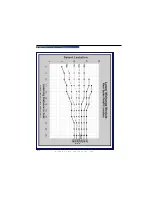
Page 83: ...W I L S O N A U D I O S P E C I A L T I E S I N C 8 1 SE C T I O N 8 TI M I N G TA B L E S FOR A GRAPHICAL ILLUSTRATION OF THIS DATA SEE NOMOGRAPH ON THE NEXT PAGE ...

Page 84: ...W I L S O N A U D I O S P E C I A L T I E S I N C ALEXANDRIA OWNER S MANUAL 8 2 T O S EE T HIS D ATA IN T ABLE F ORM S EE P REVIOUS P AGE ...

Page 85: ...W I L S O N A U D I O S P E C I A L T I E S I N C 8 3 SE C T I O N 8 TI M I N G TA B L E S FOR A GRAPHICAL ILLUSTRATION OF THIS DATA SEE NOMOGRAPH ON THE NEXT PAGE ...

Page 86: ...W I L S O N A U D I O S P E C I A L T I E S I N C ALEXANDRIA OWNER S MANUAL 8 4 T O S EE T HIS D ATA IN T ABLE F ORM S EE P REVIOUS P AGE ...

Page 87: ...W I L S O N A U D I O S P E C I A L T I E S I N C 8 5 SE C T I O N 8 TI M I N G TA B L E S FOR A GRAPHICAL ILLUSTRATION OF THIS DATA SEE NOMOGRAPH ON THE NEXT PAGE ...

Page 88: ...W I L S O N A U D I O S P E C I A L T I E S I N C ALEXANDRIA OWNER S MANUAL 8 6 T O S EE T HIS D ATA IN T ABLE F ORM S EE P REVIOUS P AGE ...

Page 89: ...W I L S O N A U D I O S P E C I A L T I E S I N C 8 7 SE C T I O N 8 1 TE T H E R BO LT TA B L E S ...

Page 90: ...W I L S O N A U D I O S P E C I A L T I E S I N C ALEXANDRIA OWNER S MANUAL 8 8 ...

Page 91: ...W I L S O N A U D I O S P E C I A L T I E S I N C 8 9 SE C T I O N 8 1 TE T H E R BO LT TA B L E S ...

Page 92: ...W I L S O N A U D I O S P E C I A L T I E S I N C ...

Page 93: ...W I L S O N A U D I O S P E C I A L T I E S I N C ...

Reviews: