background image

22


a

l e x i a

 V i

n s Ta l l aT i o n


a n d

 C

a r e

 g

u i d e

A u t h e n t i c   E x c e l l e n c e

position of the Upper Array is facilitated by the Alignment Block Steps (rotation) as well 

as the front-to-back location of the Upper Array—determined by the position of the 

Alignment Block. The position is designated by the engraved numbers in the Alignment 

Block mounting plate. Position the Alignment Block by aligning the rear of the Alignment 

Block to the number engraved on the plate as indicated in the chart in Section 6. 

There are also two spike configurations, the use of which are determined by the 

distance/ear relationship of the installation. The two rear spike configurations are: no 

spike, or a #2 spike. The table in Section 6 also contains information on the appropriate 

length spike to be used in the rear of the Upper Array.

The Tweeter module’s upper alignment plate features detents that correspond to a 

spike built into the front of the upper cross member “bridge” located above the tweeter 

module, the specific location of which determines the propagation delay position of the 

tweeter module within the Upper Array. The alignment plate contains numbered detents. 

The alignment tables in Section 6 contain the information for positioning the tweeter 

module in the array, determined by the detent in which the cross member’s spike rests.

Determine the alignment of each Upper Array and the Tweeter Module as follows. 

Repeat each step of this procedure on the left and right channels simultaneously. 

1.  Refer to the Time Alignment Charts from Section 6 in this manual and 

place them close by for easy reference. 

2.  Make sure that you are in your intended listening position.

3.  While sitting comfortably, have someone measure your ear height from 

Tweeter Detents

Summary of Contents for Alexia V

Page 1: ...peaker Placement Versus Listening Position 9 Speaker Orientation 9 S e ct i o n 2 U n c r at i n g A l e x i a V 1 3 S e ct io n 2 1 U n cr at in g Al e x ia V 14 Initial Check 14 Uncrating the Wo ofe...

Page 2: ...Materials Required 24 Install the Upper Array As Follows 25 Section 3 4 Tweeter Mo dul e Pr o pa g at io n De l ay 2 6 Section 3 5 Umbilical C o n n e ct io n s 2 7 S e ct i o n 4 F i n a l S e t u p...

Page 3: ...io n s 39 S e ct io n 5 3 Al e x ia V Ph a s e C ur ve 40 S e ct io n 5 4 Al e x ia V Impe da n ce C urve 41 S e ct i o n 6 T i m e A l i g n m e n t C h a r t s 4 3 S e ct io n 6 1 Tim e Al ig n m e...

Page 4: ......

Page 5: ...Section 1 WASP Setup W i l s o n A u d i o S p e c i a l t i e s...

Page 6: ...Neutrality is an area in your room where the speakers will sound most natural This location is where the speakers interact the least with adjacent room boundaries It is important to have a clear work...

Page 7: ...s caused by the return of the room s boundary contribution your voice is now interacting with the opposite wall At the point where you begin to hear the reflected sound of your voice you have reached...

Page 8: ...x i a V In s ta l l at i o n a n d Ca r e Gu i d e A u t h e n t i c E x c e l l e n c e When carefully followed the WASP has proven to be the most effective method for setting up Wilson Audio loudsp...

Page 9: ...he distance between the tweeters on each speaker Therefore in a long rectangular room of 12 x 18 if the speaker tweeters are going to be 9 apart you should be sitting 9 11 to 11 3 from the speaker Thi...

Page 10: ...t find the proper balance of these two factors but remember if you are partial to bass response or air and bloom do not overcompensate your adjustments to maximize these effects Overcompensated system...

Page 11: ...Sect i o n 1 1 WASP 11 W i l s o n A u d i o S p e c i a l t i e s...
Page 12: ...Upper Array Woofer...

Page 13: ...Section 2 Uncrating Alexia V W i l s o n A u d i o S p e c i a l t i e s...

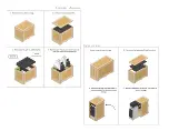
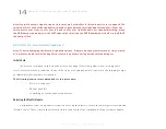
Page 14: ...ainted surface Please remove any jewelry such as rings watch es necklaces and bracelets during this process along with covering belt buckles and zippers Initial Check The Alexia V is shipped in three...

Page 15: ...side of the room Note These two Woofer Modules are very heavy and care should be taken to prevent injury Roll the Woofer Module with drivers facing forward for the best stability Uncrating the Upper...

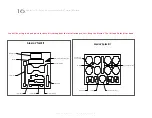
Page 16: ...g cloth Resistors 1 4 Allen Wrench 3 32 5 32 1 8 Allen Inserts 2 Caster Wrench Alexia V Tool Kit You will be using tools and parts in these kits throughout the installation process Keep the Alexia V T...

Page 17: ...les are attached to the enclosures Detach the grilles from the enclosure and remove the protective plastic covering the grille 9 Place the Upper Array with an odd serial number on the left side of the...

Page 18: ......

Page 19: ...Section 3 Assembling Alexia V W i l s o n A u d i o S p e c i a l t i e s...

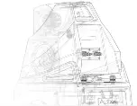
Page 20: ...of Time Alignment Charts is located in Section 6 Upper Array Assembly The Upper Array uses AA spikes on the front of the enclosure see graphic above and the built in spike receptical found at the bot...

Page 21: ...geometric time domain alignment for different distance ear height combinations This information can be found in the Time Alignment Charts in Section 6 By measuring the distance from the speaker to you...

Page 22: ...ngth spike to be used in the rear of the Upper Array The Tweeter module s upper alignment plate features detents that correspond to a spike built into the front of the upper cross member bridge locate...

Page 23: ...ing where the rear spike on the bottom of the mid module will rest The third table Midrange Spike Length determines whether or not there is a spike in stalled into the rear of the module The fourth ta...

Page 24: ...e front to back location of each module along with the use of the proper length of rear spike of the upper arrays Refer to the Alexia V Time Alignment Charts and the procedure in the previous section...

Page 25: ...t Block Position Using the rear edge of the Alignment Block as the guide align the block to the proper front to back setting for the Upper Array Once the block is in its proper position lock it down b...

Page 26: ...g the Tweeter Module support the front of the module to ensure it does not slide forward 1 Locate the number on the tweeter alignment plate on the up per plane of the tweeter that corresponds to the d...

Page 27: ...tive terminal on the biding post labeled High Frequency on the Upper Array Connect the BLACK cable to the BLACK negative terminal Tighten binding post nut with the 1 2 Driver found in the Tool Kit Do...

Page 28: ......

Page 29: ...Section 4 Final Setup W i l s o n A u d i o S p e c i a l t i e s...

Page 30: ...ker later Screw the spike nut combo into the diode housing until the nut is against the diode Be careful that the nut does not turn while inserting and threading spikes into the diode Note Do not tigh...

Page 31: ...ake care to mark the exact location of the Alexia Vs with masking tape to ensure the speakers can be returned to their exact set up position 2 If leaning the Alexia V to the side safely is not an opti...

Page 32: ...ble level and determine if the Alexia V is level or which side of the enclosure is lower than the rest making the enclosure uneven 2 To find out which spike is lowest grasp the Alexia V enclosure and...

Page 33: ...otective film when the speaker surface is cold can damage the paint surface 2 Slowly remove the film from the top down large sections at a time gently pulling the film downward and outward Note Tearin...

Page 34: ...provide precise level match ing for the midrange and tweeter drivers correspondingly The resistors also act as ultra high quality fuses which open before a driver can be damaged by excess power i e p...

Page 35: ...on Audio Dealer or on the Wilson Audio Online Store Only use Wilson Audio replacement resistors in your Alexia V Note If you notice the sonic qualities of your system degraded or worsen you may have r...

Page 36: ......

Page 37: ...Section 5 Specifications W i l s o n A u d i o S p e c i a l t i e s...

Page 38: ...l Dimensions System Weight Per Channel Approximate Shipping Weight Rear Ported Rear Vented Sealed One 8 inches 20 32 cm Paper Pulp One 10 inches 25 4 Paper Pulp One 7 inch 17 78 cm Paper Pulp Composit...

Page 39: ...G UNLESS OTHERWISE SPECIFIED TOLERANCES ARE FRACTIONS DECIMALS ANGLES 1 32 035 5 MATERIAL FINISH DO NOT SCALE DRAWING 3 4 5 6 7 8 8 7 6 5 4 3 THE INFORMATION CONTAINED IN THIS DRAWING IS THE SOLE PROP...

Page 40: ...40 Al e x i a V In s ta l l at i o n a n d Ca r e Gu i d e A u t h e n t i c E x c e l l e n c e Section 5 3 Alexia V Phase Curve...

Page 41: ...Sect i o n 5 4 Al e x i a V Im p e da n ce Cu rv e 41 W i l s o n A u d i o S p e c i a l t i e s Section 5 4 Alexia V Impedance Curve...

Page 42: ......

Page 43: ...Section 6 Time Alignment Charts W i l s o n A u d i o S p e c i a l t i e s...

Page 44: ...ke No Spike Upper Array Alignment Block Position Midrange Spike Length Ear Height Ear Height Ear Height Listening Distance Listening Distance Listening Distance Upper Array Alignment Block Step Sect i...

Page 45: ...ofalignment block is 1 8 fromback edgeof alignment plate Back ofalignment block lines up with back edgeof alignment plate Pleasecontact yourdealer 46 in 117 cm 7 7 7 6 6 6 6 6 6 6 5 5 5 5 44 in 112 c...

Page 46: ......

Page 47: ...Section 7 Warranty W i l s o n A u d i o S p e c i a l t i e s...

Page 48: ...product Contact Wilson Audio Dealer Technician or a service or repair center authorized by Wilson Audio to service or repair the product Contact Wilson Audio at 1 801 377 2233 for information on locat...

Page 49: ...n two 2 years of date of shipment to the description of the defect Dealer owned demonstration equipment sold at retail within two 2 years of date of shipment to the Dealer is warranted to the first re...

Page 50: ...s and Literature Custom Loudspeaker Covers Installation Tools and Accessories New Grilles and Diffraction Blankets WilsonGloss Care Products and Kits Wilson Signature Apparel Upgrade Spikes and Bindin...

Reviews: