background image

A

l e x i A

  O

w n e r

s

  M

A n u A l

32

W i l s o n   A u d i o   S p e c i a lt i e s

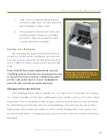
tion delay adjustment. The spike also provides proper coupling of the Upper Array to 

the Woofer Module. Shorter “AA” spikes are always installed in the front two positions 

(the threaded holes located near the bottom front of the enclosure). The spike-type is 

stamped in the round top of the spike. The two “AA” spikes screw into the Upper Array 

as shown in Figure 4. The spikes should be screwed in all the way, until they are hand 

tight. Do not over tighten spikes. 

Section 3.2—Alexia Propagation Delay Adjustment 

Room Setup

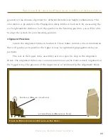
As indicated in Figure 

6, the Alexia system al-

lows for different listening 

distances (away from the 

speakers) and listening ear 

heights (measured distanc-

es from the floor to your 

ear). For each distance/ear 

height combination there is 

a unique alignment geom-

etry. 

To make correct in-

home set up of the Alexia 

possible without test 

equipment, Wilson Audio 

has measured the correct 

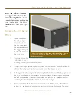
f

igure

 5—t

Op


Of


the

 w

OOfer

 M

Odule

with


spike


guides


And


reAr


spike


receptAcle

U

pper

 A

rrAy

 S

pike


p

lAcement

 G

Uide

r

otAtion

 l

Adder

p

Ainted

 i

nner

 e

dGe


And


top


of

 W

oofer

 m

odUle

f

orWArd

/B

Ack


n

UmBered

 t

rAck

Summary of Contents for Alexia

Page 1: ...A l e x i a O w n e r s M a n u a l ...

Page 2: ...mation con t ain ed h erein is su bject t o ch an g e wit h o ut notic e Cur rent Revision 1 8 If you are in need o f a mo re recen t man u al please co nta c t y our dea l er The information in this manual is the so le pro per t y o f W ilso n Au dio Specialtie s Inc An y reproduction in whole or in part wit h o u t t h e express wr it t en per missio n of W ilson Au di o Specialties Inc is prohi...

Page 3: ...l t e r E ff e c t 1 5 S e c t i o n 1 4 R e s o n a n c e s 1 6 S t r u c t u r a l R e s o n a n c e 1 6 V o l u m e R e s o n a n c e 1 6 S e c t i o n 1 5 Y o u r R oom 1 7 R o o m S h a p e s 1 7 A l e x i a I n A D e d i c a t e d H o m e T h e a t e r 1 9 S p e a k e r P l a c e m e n t V e r s u s L i s t e n i n g P o s i t i o n 1 9 S p e a k e r O r i e n t a t i o n 2 0 S u m m a r y 2...

Page 4: ...c t i o n 3 4 T w e e t e r M o d u l e P r o p a g a t i o n D e l ay 3 9 S e c t i o n 3 5 U m b i l i c a l C o n n e c t i o n s 3 9 S e c t i o n 4 F i n a l S e t u p 4 1 S e c t i o n 4 1 S p i k i n g t h e A l e x i a 4 3 S p i k e A s s e m b l y 4 3 I n s t a l l a t i o n P r o c e d u r e 4 3 S e c t i o n 4 2 L e v e l i n g t h e A l e x i a 4 5 S e c t i o n 4 3 R e mo v i n g t h ...

Page 5: ...p e c i f i c a t i o n s 6 1 S e c t i o n 7 2 A l e x i a D i m e n s i o n s 6 4 S e c t i o n 8 P r o p a g a t i o n D e l ay T a b l e s 6 5 S e c t i o n 8 1 P r o p a g a t i o n D e l ay T a b l e s 6 7 S e c t i o n 9 W a r r a n t y I n f o r ma t i o n 6 9 S e c t i o n 9 1 W a r r a n t y I n f o r ma t i o n 7 1 L i m i t e d W a rr a n t y 7 1 C o n d i t i o n s 7 1 R e m e d y 7 2...

Page 6: ...W i l s o n A u d i o S p e c i a lt i e s ...

Page 7: ...S e c t i o n 1 I n Yo u r R o o m ...

Page 8: ......

Page 9: ...speaker Therefore we offer the following section which will present some guidelines on room acoustics and their interactions with loudspeakers While we will also outline some detailed suggestions on the setup of the Alexia we strongly suggest that you have your local Wilson Audio dealer perform the final speaker voicing with you Wilson dealers are specially trained in setting up Wilson loudspeaker...

Page 10: ...ll sound more tonally cor rect and less spatially diffuse your assistant can now precisely localize the exact origin of your voice When you hear this transition you have entered the inner edge of the Zone of Neutrality Place a piece of tape on the floor to mark this location Although it will vary from room to room the zone in most rooms begins between two and a half to three feet from the rear wal...

Page 11: ...s of Neutrality one for each channel Theoretically the Zone of Neutrality for any room runs like a path parallel to the walls all around the room Adjacent to very large windows and open doors the outer edge of the Zone of Neutrality moves closer to the wall and becomes wider If you were to extend the inner and outer boundaries of the Zone for the sidewalls and the front wall behind the speakers th...

Page 12: ...om by clapping your hands sharply in the middle of the room and listening for the characteristic sound of the echo in the mid range Slap echo destroys the sound quality of a stereo system in two ways It adds harshness to the upper midrange and treble by storing time domain smearing energy It destroys the delicate phase relationships which help to establish an ac curate soundstage Slap echo see Fig...

Page 13: ... environments heavy stuffed furnishings reduce slap echo somewhat Unfortunately their effectiveness is not predictable Diffusers are sometimes also used to very good subjective effect particularly in quite large rooms Sound absorbent materials such as described above will alter the tonal characteristic of the room by making it sound deader less bright and alive and quieter These changes usually ma...

Page 14: ...Tonal balance Resolution of low level detail Soundstaging Standing waves are more difficult to correct than slap echo because they tend to occur at a lower frequency Absorbent materials such as Pinta Acoustic Sonex are ineffective at controlling reflections in the bass region Moving speakers about slightly in the room is for most people their only control over standing waves Sometimes a change of ...

Page 15: ...ted toward a microphone or listener from a distance The first sound to reach the microphone is the direct sound followed by a delayed reflected sound At certain frequencies cancellation occurs because the reflected sound lags in phase rela tive to the direct sound This cancellation is most apparent where the two frequencies are 180 degrees out of phase Further there is augmentation at other freque...

Page 16: ... resonances To give you an idea of what the perfect wall would sound like imagine rapping your hand against the side of a mountain Structural wall resonances generally occur in the low to mid bass frequencies and add a false fullness to the ton al balance They too are more prominent at louder levels but their contribution to the sound of the speaker is more progressive Rattling windows picture fra...

Page 17: ...y control Section 1 5 Your Room Room Shapes Standing waves are pressure waves propagated by the interaction of sound and op posing parallel walls This interaction creates patterns of low and high acoustical pres sure zones that accentuate and attenuate particular frequencies Those frequencies are dependent on room size and dimension There are three basic shapes for most rooms square rectangular an...

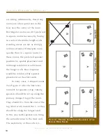
Page 18: ...referred speaker position for spatial placement and midrange resolution would be on the longer walls Bass response would be reinforced by speaker placement on the short walls In many cases L shaped rooms See Figure 2 offer the best envi ronment for speaker setup Ideally speakers should be set up along the primary longest leg of the room They should fire from the end of the leg short wall toward th...

Page 19: ...ized for the best sound quality Odd numbers of chairs arranged in rows work best as this will allow a single chair to be positioned in the center This approach will also provide the best overall sound for the greatest number of seats Speaker Placement Versus Listening Position The location of your listening position is as important as the careful setup of Alex ia speakers The listening position sh...

Page 20: ...ng primary reflection This can cause out of phase cancellations or comb filtering which will cancel some frequencies and change the tonal balance of the mu sic The Wilson Audio Setup Procedure Section 1 2 is the best method with which to position your loudspeakers Start with the speakers about 18 from each wall and if you need to move them relative to the side wall move them away from the wall not...

Page 21: ...he Alexia should be positioned as outlined in this section Ideally the speakers should not be positioned too far from the listener if maximum resolution of low level detail is required If possible the speakers should be positioned out into the room slightly asymmetrically vis a vis the side and rear walls The speak ers should be toed in toward the listener preferably so that the listener at his se...

Page 22: ...W i l s o n A u d i o S p e c i a lt i e s ...

Page 23: ...S e c t i o n 2 U n c r a t i n g A l e x i a ...

Page 24: ...W i l s o n A u d i o S p e c i a lt i e s ...

Page 25: ...ng company immediately for insurance verification The following items are recommended for this procedure Electric Screwdriver Phillips head drive bit Masking tape for use in speaker setup Uncrating the Woofer Module A minimum of two strong adults is required to set up the Alexia Locate the two largest crates labeled Woofer Module These contain the woofer enclosures and are the first components of ...

Page 26: ...l kit Remove these 3 Make sure the thumb bolt that secures the Tweeter is tight before moving 4 When removing the upper modules take care so as not to hit the modules on the crate and scratch the paint Using the small shelf on the rear of the module tilt it so there is access to the bottom side Slide the other hand under the Upper Array for support and carefully lift the enclosure out of the crate...

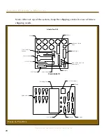
Page 27: ... enclosure 4 AA Spikes 2 2 Spikes 2 3 Spikes 2 4 Spikes 1 1 2 Nut Driver 1 Polishing Cloth 8 Woofer Module Spike assembly with conical diode 8 Aluminum Disk Spike Floor Protectors 1 Allen Driver Handle 1 3 32 Allen Insert 1 5 32 Allen Insert 1 1 8 Allen Insert 1 7 16 Combination Wrench 1 9 16 Combination Wrench 1 Caster Wrench 1 3 8 Allen Wrench 1 3 16 L shaped Allen Wrench 2 9 0 Ohm Resistors 2 5...

Page 28: ... s o n A u d i o S p e c i a lt i e s Diode Resistors Aluminum Spike Pads Allen Driver 3 8 Driver 1 2 Nut Driver Castor Wrench Allen Wrench 7 16 and 9 16 Wrench Resistors 3 32 5 32 and 1 8 Allen Inserts Alexia Tool Kit Figure 3 Tool Kits Spike with Nut Polishing Cloth 1 1 2 Set Screws AA Spike 2 Spike 4 Spike 3 Spike Alexia Spike Kit ...

Page 29: ...S e c t i o n 3 I n i t i a l S e t u p ...

Page 30: ...W i l s o n A u d i o S p e c i a lt i e s ...

Page 31: ...on Tables Section 8 Known listening position Masking Tape Take a moment to familiarize yourself with the top of the Woofer Module A com plete set of Propagation Delay Correction Tables is located in Section 8 Upper Array Assembly The Upper Array uses the combination of a captive spike or the addition of one of three different length accessory spikes installed into the bottom of its enclosure The s...

Page 32: ...ntil they are hand tight Do not over tighten spikes Section 3 2 Alexia Propagation Delay Adjustment Room Setup As indicated in Figure 6 the Alexia system al lows for different listening distances away from the speakers and listening ear heights measured distanc es from the floor to your ear For each distance ear height combination there is a unique alignment geom etry To make correct in home set u...

Page 33: ...tem for your listening position Alignment Procedure Locate the Alignment tables in Section 8 These tables contain critical information that will guide you to position the Upper Arrays for optimized propagation delay ad justment The rear of the Upper Array assembly rests on a specific step in the Alignment Block The alignment tables also contains information on the front to back alignment of the Up...

Page 34: ...on the appropriate length spike to be used in the rear of the Upper Array The Tweeter module s upper plate features detents that correspond to a spike built into the front of the upper cross member located above the tweeter module see Fig ure 7 the specific location of which determines the propagation delay position of the tweeter module within the Upper Array The alignment plate contains numbered...

Page 35: ...be when listening to music see Figure 7 5 Now measure the distance on the floor from the point on the floor below your ear to the base of the loudspeaker as shown in Figure 6 6 Refer to the Propagation Delay Tables Section 8 and locate the corre sponding ear height for each module There are four charts for the Upper Array The first Alexia Upper Array Spike Length is a table determin ing the rear s...

Page 36: ...sition indicating the block location for that module Set this information aside as you will refer to it in the next section See Figure 7 9 Make a mark on the third chart labeled Alexia Upper Array Alignment Block Step indicating Upper Array spike s resting position on the align ment block Set this information aside as you will refer to it in the next sec tion See Figure 7 10 Refer to Table Num ber...

Page 37: ... to the Alexia Propagation delay Tables and the procedure in the previous section to determine the correct Aspherical Propagation delay spikes as necessary S e ct i o n 3 3 M o u n t i n g t h e U pp e r A r r ay Figure 10 Slide the Upper Array s front spikes along the guides in the top of the Woofer Module keeping the rear of the Upper Array elevated to avoid scratching the Woofer Module ...

Page 38: ...per Array Figure 7 Once the block is in its proper position lock it down using the 3 8 Allen wrench 4 Refer to the table labeled Alexia Upper Array Alignment Block Step Block Position table With the front spikes pointing down carefully lower the Upper Array between the alignment wings and set it on top of the woof er enclosure see Figure 10 There are alignment tracks that accommodate the spikes an...

Page 39: ...hat corresponds to the detent indicated in the table see Fig ure 9 6 Slide the tweeter such that the downward pointing spike of the Array bridge aligns with the appropriate numbered detent 7 Retighten the oval thumb bolt ensuring that the spike rests properly in its appropriate detent see Figures 9 and 11 Section 3 5 Umbilical Connections The correct connection of the two umbilicals to the Upper A...

Page 40: ...e black lug of the cable to the BLACK negative termi nal 3 Locate the cable marked High Freq Connect the RED lug to the RED terminal on the connection labeled High Frequency on the Upper Array Connect the black lug of the cable to the BLACK negative terminal Note Please ensure that you do not invert the polarity of the umbilicals in the Alexia Such an inversion will produce entertaining ambient ef...

Page 41: ...S e c t i o n 4 F i n a l S e t u p ...

Page 42: ...W i l s o n A u d i o S p e c i a lt i e s ...

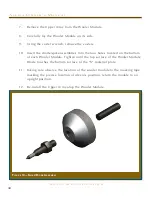
Page 43: ... turn while inserting and threading spikes into the diode 3 Place the set screw into the other end of the diode with the Allen head toward the spike This will ensure that if for any reason you have to remove your Alexia spikes you will be able to withdraw the set screw safely using the supplied Allen wrench Screw the set screw into the diode until it meets the spike see Figure 13 4 Assemble the re...

Page 44: ... spike assemblies into the four holes located on the bottom of each Woofer Module Tighten until the top surface of the Woofer Module Diode touches the bottom surface of the X material plate 11 Taking care observe the location of the woofer module to the masking tape marking the precise location of Alexia s position return the module to an upright position 12 Re install the Upper Array atop the Woo...

Page 45: ...oothed pliers 3 Lengthen the appropriate spike or spikes not the Woofer Module Spike di ode on the set screw on the lower side until the Alexia is level 4 If the speaker is leaning to the left lengthen both Woofer Module spikes on the right hand side of the speaker If the speaker is leaning right lengthen the left hand spikes Lengthen the spikes incrementally checking and re checking the level unt...

Page 46: ...e rests 7 Once all adjustments have been made with the 9 16 wrench provided tighten the nut on the spike to the diode DO NOT OVERTIGHTEN Snug is tight enough Section 4 3 Removing the Protective Film To protect the finish of the Alexia during final manufacture shipment and setup in your listening room we have applied a removable layer of protective film over the finish We recommend that this film b...

Page 47: ... in your Alexias Changing the value or brand of resistor will have a deleterious affect on the sonic performance of your loudspeakers and will void your Wilson Audio Warranty Midrange and Tweeter Resistors The Midrange Level which consists of a 2 55 ohm 2x5 1 in parallel See Figure 16 resistor assembly for the mid and Tweeter Level which consists of 4 5 ohm 2x9 0 in parallel resistor assembly for ...

Page 48: ...rn affects the way the Alexia s woofers couple to the amplifier Both of these resistors are pre installed in the base of the Bass Module and should not be changed by the end user A l e x i a O w n e r s M a n u a l 48 W i l s o n A u d i o S p e c i a lt i e s Figure 16 Mid Tweeter Resistor are attached to heatsinks with Allen hardware ...

Page 49: ...S e c t i o n 5 C a r e o f Yo u r A l e x i a ...

Page 50: ...W i l s o n A u d i o S p e c i a lt i e s ...

Page 51: ...eakers Blow off all loose dust Using the special dust cloth as a brush gently whisk off any remaining loose dust Shake out the dust cloth Dust the finish using linear motions in one direction parallel to the floor Avoid using circular or vertical motions Because the paint requires a period of several weeks to fully cure we recommend that no cleaning fluids such as glass cleaners be used during thi...

Page 52: ... of their speaker grilles In addition to basic black Wilson Audio offers a variety of grille colors to match most WilsonGloss finishes Contact your local dealer for grille cloth samples or to order replacement grilles for Alexia Break in Period All audio equipment will sound best after its components have been broken in for some period of use Wilson Audio breaks in all drivers for approximately 12...

Page 53: ...e composites meets and exceeds the highest of ANSI test standards for its use while offering very tight tol erances high hardness uniform density and dimensional stability Adhesive Wilson Audio has conducted exhaustive research into the best adhesives to perma nently bond our speaker enclosures This is often an overlooked element crucial to the proper performance of a loudspeaker Correct modulus o...

Page 54: ...tructural aspects are combined allowing Wilson Audio to deliver a product that maintains the strictest structural tolerances durability and reliability This also means that the Alexia will have consistent repeatable performance unaffected by the climatic conditions anywhere in the world Fi nally like all Wilson products Alexia is hand crafted with meticulous attention to detail with an unwavering ...

Page 55: ...S e c t i o n 6 T r o u b l e s h o o t i n g ...

Page 56: ...W i l s o n A u d i o S p e c i a lt i e s ...

Page 57: ...l o o s e W h e n a t w e e t e r o r m i d r a n g e d r i v e r i s n o t w o r k i n g o r i s o u t o f p h a s e t h e A l e x i a w i l l n o t i m a g e p r o p e r l y D o u b l e c h e c k y o u r c o n n e c t i o n s f o r r e d t o r e d a n d b l a c k t o b l a c k P l ay m u s i c a t a l o w l e v e l a n d l i s t e n t o e a c h d r i v e r i n e a c h c h a n n e l Yo u m ay h a...

Page 58: ...s e r e s i s t o r s w e r e c a r e f u l l y c h o s e n f o r t h e o v e r a l l s o n i c a n d t h e r m a l p e r f o r m a n c e P l u g y o u r a m p l i f i e r i n t o t h e w a l l a n d t u r n i t o n L i s t e n t o t h e c h a n n e l a t a l o w l e v e l Th e d r i v e r s h o u l d n o w b e o p e r a t i n g c o r r e c t l y C h e c k t o s e e i f y o u r s p e a k e r c a b...

Page 59: ...C o n t i n u e t o t h e n e x t s t e p Tu r n t h e a m p l i f i e r o f f a n d d i s c o n n e c t i t f r o m t h e AC w a l l o u t l e t D i s c o n n e c t t h e s p e a k e r c a b l e l e a d s t o t h e a m p l i f i e r a n d t u r n t h e a m p l i f i e r o n a g a i n Yo u h av e a s h o r t i n y o u r s p e a k e r c a b l e s C h e c k f o r f r ay e d e n d s h o l e s f r o m...

Page 60: ...W i l s o n A u d i o S p e c i a lt i e s ...

Page 61: ...S e c t i o n 7 S p e c i f i c a t i o n s ...

Page 62: ...W i l s o n A u d i o S p e c i a lt i e s ...

Page 63: ...e Overall Dimensions Alexia Weight Per Channel Sealed X Material Rear Vented X S Material Rear Ported X Material One 8 inch 20 32 cm Paper Pulp One 10 inches 25 4 cm Paper Pulp 7 inch 17 78 cm Paper Pulp Composite 1 inch 2 54 cm Doped Silk Fabric 90 dB one watt at one meter at 1Khz 4 ohms minimum 2 ohms 80 Hz 20 watts per channel 20 Hz 32 kHz 3 dB with port contribution Height 53 1 4 inches 135 29...

Page 64: ...A l e x i a O w n e r s M a n u a l 64 W i l s o n A u d i o S p e c i a lt i e s Section 7 2 Alexia Dimensions Figure 17 ...

Page 65: ...S e c t i o n 8 P r o pa g a t i o n D e l a y Ta b l e s ...

Page 66: ...W i l s o n A u d i o S p e c i a lt i e s ...

Page 67: ...4 4 4 38 3 2 3 3 3 3 4 4 4 4 4 4 36 3 3 3 3 4 4 4 4 4 4 4 4 Alexia Upper Array Spike Length Ear Height inches Listening Distance 8 9 10 11 12 14 16 18 20 22 24 26 48 2 5 7 5 3 4 5 7 9 7 8 8 5 9 5 5 46 5 5 2 3 5 5 6 5 9 10 5 8 5 10 10 11 6 5 44 3 4 7 8 9 5 11 12 10 10 5 11 5 6 5 6 5 42 6 7 5 9 10 11 5 9 5 10 5 12 12 7 8 8 5 40 5 11 12 13 13 11 12 7 5 8 5 8 5 8 5 10 38 8 5 14 11 12 12 13 8 9 9 10 10...

Page 68: ...7 8 8 8 9 38 2 3 4 4 5 6 7 7 8 8 8 9 36 2 3 4 4 5 6 7 7 8 8 8 9 Ear Height inches Listening D istance Alexia T weeter D etent P osition 8 9 10 11 12 14 16 18 20 22 24 26 48 6 8 10 3 4 6 7 6 7 7 8 5 46 8 2 3 4 5 7 8 7 8 8 9 6 44 2 3 5 6 7 8 9 8 8 9 6 6 42 4 5 6 7 8 7 8 9 9 6 7 7 40 3 7 8 9 9 9 9 5 7 7 7 8 38 5 9 7 8 8 9 6 7 7 8 8 8 36 7 8 9 9 7 7 7 8 8 8 9 9 Alexia U pper A rray A lignment B lock S...

Page 69: ...S e c t i o n 9 Wa r r a n t y I n f o r m a t i o n ...

Page 70: ...W i l s o n A u d i o S p e c i a lt i e s ...

Page 71: ... 2 The product must have been professionally installed by the Wilson Audio dealer that sold the product to the customer FAILURE TO COMPLY WITH EITHER REQUIREMENT NO 1 OR REQUIREMENT NO 2 WILL RESULT IN THE WARRANTY PERIOD BEING LIMITED TO A PERIOD OF 90 DAYS ONLY Conditions This Limited Warranty is also subject to the following conditions and limitations The Limited Warranty is void and inapplicab...

Page 72: ...erein have been met the purchaser s sole remedy under this Lim ited Warranty shall be to 1 contact an authorized Wilson Audio Dealer within the Warranty Period for service or repair of the product without charge for parts or labor which service or repair at the Dealer s option shall take place either at the location where the product is installed or at the Dealer s place of business or 2 if purcha...

Page 73: ...ler owned demonstration equipment sold at retail within two 2 years of date of shipment to the dealer is warranted to the first retail customer to be free of manufacturing defects in materials and workmanship for the same time periods as if the product had originally been bought for immediate resale to the retail customer Wilson Audio products are warranted for a period of 90 days unless extended ...

Page 74: ...p e c i a lt i e s an exclusion or limitation of incidental or consequential damages so the above limi tations or exclusions may not apply to you This Limited Warranty gives you specific legal rights and you may also have other rights which vary from state to state ...

Reviews: